
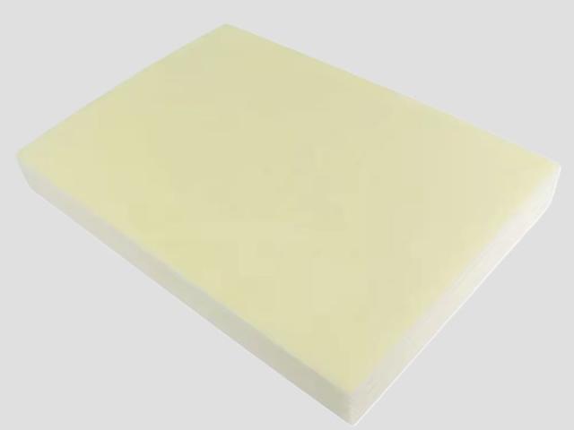
XPE foam is made in two stages that are easy to confuse and impossible to swap: first the polyethylene is cross-linked into a three-dimensional network, then it is foamed. Cross-linking raises the polymer’s melt strength so that the gas produced in the second stage forms closed cells instead of tearing the sheet apart. Reverse the order and what comes out is not XPE.
That ordering explains a second thing this page spends most of its length on. When a delivered sheet does not meet specification, the three properties people test (density, compression set, dimensional change) each respond to more than one stage, so none of them names the stage that failed. The last half of the page is about reading them together.
What goes into it
The base is low-density polyethylene. To it are added a blowing agent and a cross-linking agent — in our chemical route azodicarbonamide (ADC) as the blowing agent and dicumyl peroxide (DCP) as the cross-linking agent — plus colour masterbatch and such functional additives as flame retardants or antistatic agents. There is no solvent and no water in the process; the gas that forms the cells comes from the decomposition of the blowing agent.
The quantities are the process know-how, and this page does not give them. What matters for a buyer is only that the dosing of these additives is set before the sheet is extruded and cannot be corrected afterwards.
Two cross-linking routes
| Chemical cross-linking | Radiation cross-linking | |
|---|---|---|
| Mechanism | DCP decomposes under heat and forms carbon–carbon bonds between chains | An electron beam breaks C–H bonds, and the radicals that form recombine across chains |
| Where the cross-links form | Throughout the sheet, with the extruder and oven doing the work | Where the beam reaches; penetration falls with thickness, so thick sheet needs both sides |
| Typical product | XPE, IXPE | IXPE, and thin sheet generally |
| What it allows | Thicker single layers | Very thin sheet, 0.1 mm upward, with even properties |
Both routes give closed-cell cross-linked polyethylene. The practical difference a buyer meets is thickness: the electron beam is how IXPE reaches 0.1 mm, because chemical foaming of a sheet that thin is difficult to control. See what IXPE material is for the thin-sheet route in detail.
The process, end to end
- Mixing and compounding. Resin, blowing agent, cross-linking agent and additives are blended to a uniform compound. Uneven blending here shows up later as uneven density within a sheet.
- Extrusion to sheet. The compound is extruded into a continuous sheet of the target gauge. At this point it is uncross-linked and unfoamed — a dense plastic sheet.
- Cross-linking. Either the sheet passes through an oven that activates the DCP (chemical), or it passes under an electron beam (radiation). The polymer becomes a network.
- Foaming. The sheet enters a foaming oven at a higher temperature, where the blowing agent decomposes and expands the cross-linked sheet.
- Cooling and stabilising. The expanded sheet is cooled under controlled conditions; this is where the cell structure is locked in.
- Finishing. Trimming, slitting to width, corona treatment for adhesion, lamination, adhesive coating, die-cutting, winding.
Steps 3 and 4 are the reason thickness has a ceiling. In a thick sheet the outside of the material reaches foaming temperature before the inside does, so the two regions expand at different moments and the sheet can be denser in the middle than at the faces. That is why single-layer XPE stops at 15 mm and anything from 15 to 200 mm is heat laminated from thinner sheets instead. The bond layer that adds is discussed in foam lamination.
Three properties, three different inspection sheets
What is measured on the finished sheet is not a record of the process. These three are the ones most often quoted, and each is a different standard:
| Property | Standard and conditions | What it describes |
|---|---|---|
| Apparent density | GB/T 6343 | Mass per unit volume, fixes the expansion ratio grade |
| Compression set | GB/T 6669, 23±2 °C for 22 h | How much of a compression does not come back |
| Dimensional change | GB/T 8811, 70±2 °C for 22 h | How much the sheet shrinks or grows when heated, machine and cross direction separately |
Three properties, and no stage of the process produces exactly one of them.
Why no property names a stage
It is tempting to read density as a foaming parameter and compression set as a cross-linking parameter. Both readings are wrong.
- Density is set by how much blowing agent gas is produced and by how well the cross-linked network holds it. Under-cross-link and the gas escapes, so a sheet dosed for 20× comes out denser than 50 kg/m³. Over-dose the blowing agent and it comes out lighter than the grade. One number, two inputs.
- Compression set is mostly a cross-linking result — a well-formed network recovers — but it also depends on cell wall thickness, which depends on density, and on whether the cells collapsed during cooling.
- Dimensional change is a residual-stress measurement. Sheet that was stretched during extrusion and cooled under tension shrinks on reheating. It can also be raised by incomplete cross-linking, which lets the network relax further in the oven.
So the same complaint — “this sheet came out wrong” — can be a dosing problem, a cross-linking problem, or a cooling and tension problem, and the property that failed is not the one that names the cause.
The wrong diagnosis that looks right
The most common misreading is to treat low density as a dosing error and start adjusting the blowing agent. Suppose a 25× grade (nominal 40±4 kg/m³) measures about 35 kg/m³ — within tolerance, but at the light end — and the complaint is that parts under load flatten.
The instinct is to blame the blowing agent, because the density is the number that moved. But 35 kg/m³ is inside the grade, so the density is not out of specification; what is out of specification is the compression set, and if the cross-link is incomplete the network is too weak to hold the gas and too weak to recover, and both symptoms arrive together. Correcting the blowing agent would push the density back up and leave the recovery exactly as it was.
The test that separates them is not another density measurement. It is compression set against the table, on the same sample, at the same time.
The second misreading: cooling stress
The mirror case is a sheet whose density and compression set are both fine but which shrinks badly when a customer thermoforms or laminates it. That is not a foaming defect at all; it is residual stress from the extrusion and cooling stages, and the material was within specification as delivered. It shows up as dimensional change, and it is why that column is measured in two directions: shrinkage is usually larger along the machine direction, because that is the direction the sheet was drawn.
A third class: unevenness within one sheet
Density is reported as one number per grade, but it is measured on a specimen, not on the whole roll. A sheet can pass at the sampled point and still vary across its width or along its length, and the customer meets the variation as inconsistent feel, inconsistent die-cutting depth or inconsistent compression between parts cut from the ends of the same roll. This is a blending and oven-uniformity issue, and the number that would describe it — a within-sheet density spread — is one we do not publish.
The order that actually works
Given the overlap above, the reliable way to read a failure is by elimination rather than by symptom:
- Density first. Weigh and measure against GB/T 6343. If the sample is outside the grade band, the problem is upstream of everything else and the other properties should not be read until it is settled.
- Compression set second. If density is in band and the part fails under load, measure GB/T 6669. Out of band on a grade that should hold points at the cross-link and the cooling, not at the blowing agent.
- Dimensional change third. If both of the above are fine and the customer’s problem appears during their own heating step, read GB/T 8811 in both directions before assuming a material fault.
Reading them in this order stops the most expensive mistake in the sequence: changing a process parameter in response to a property that was measured before the real fault was isolated.
A worked example
Take 25× XPE, nominal 40±4 kg/m³, compression set ≤10%, dimensional change ≤6% cross and ≤8% machine.
The delivered sheet measures 41 kg/m³, compression set 14%, dimensional change 5% cross / 7% machine. The customer reports that pads under sustained load flatten within months.
Read in order: density 41 is in band, so the grade was produced correctly and the blowing agent is not the story. Dimensional change is inside both limits, so there is no large residual stress to explain it. Compression set at 14% against a ≤10% ceiling is the only row out of specification, and it is the row that matches the complaint. The diagnosis is a weak network — under-cross-linked for the grade — and the response is at the cross-linking stage, not the foaming stage.
Note what the numbers did here: two of the three properties were normal, and one was wrong, and the complaint corresponded to the one that was wrong. That is the easy case. When two are out of band the elimination order matters more, because the first out-of-band reading invalidates the second.
What we do not publish
The properties above are the ones on our data sheet. The following are deliberately not given, and asking for them will get you a conversation rather than a number:
- Cross-link density and gel content — the direct measures of the network, and the process parameters behind them.
- Cell pore diameter and cell size distribution.
- Within-sheet density spread — the uniformity figure described above.
- Defect rates and process parameters — temperatures, line speeds, dwell times, beam dose.
None of these is a property you can accept a delivery against, and publishing them would invite specifications that cannot be checked at goods-in. Accept against the three GB/T properties, and use samples where the shape of the part matters.
Common questions
Is XPE cross-linked before or after foaming?
Before. The cross-linked network is what holds the gas as closed cells; foam first and the cells rupture. This single ordering is the difference between XPE and ordinary LDPE foam.
What is the difference between XPE and IXPE in manufacturing?
Mainly the cross-linking route and the thickness it permits. Radiation cross-linking reaches well under the 3 mm floor of chemically foamed XPE, down to 0.1 mm; see IXPE material.
Why does thicker sheet need lamination?
Because the outside foams before the inside, giving the sheet a density gradient through its thickness. Above 15 mm the gradient is bad enough that we laminate thinner sheets instead, up to 200 mm.
Can I tell the density by looking at it?
No. A caliper measures thickness, not density, and two grades of the same colour look alike. Density has to be weighed against volume.
Why does one grade have a tolerance band?
Because the expansion ratio has a tolerance of its own. 25× material is nominally 40±4 kg/m³, so 36 to 44 are all in grade.
What Bofeng Foam supplies
Bofeng Foam produces XPE, IXPE and IXPP foam in Zhuhai, Guangdong, with a 10,000 m² plant, five production lines and 5,000 tonnes of annual capacity. XPE from 3× to 40×, apparent density 26.8–300 kg/m³, single layer 3–15 mm; IXPE single layer 0.1–15 mm; heat-laminated multi-layer 15–200 mm; width 500–2000 mm; calendered, corona treated, laminated, adhesive backed, die-cut or punched.
If you are qualifying a delivery, the useful message contains the grade and the property that failed, with the measured value and the method. We will tell you whether it is inside the band before discussing the cause.
See the XPE performance table · Ask about a grade or a test result
See also what XPE foam is, how to choose XPE density, choosing density and thickness together, IXPE material, foam lamination, what foam is made of and all foam materials.