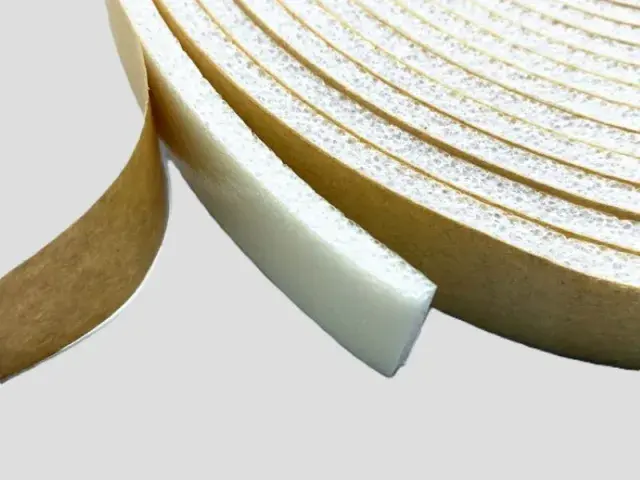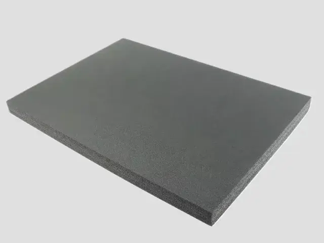

- Material: XPE foam, IXPE foam
- Expansion ratio: 25 times (40 kg/m³), 30 times (33 kg/m³)
- Thickness: XPE single layers 3–15 mm; IXPE single layers 0.1–15 mm; thermally laminated multilayers 15–200 mm. Confirm the finished construction.
- Colour: black and gray (colour can be customized)
- Flame retardant grade: UL94 HF-1
Customization
Made to order: density, thickness, colour and shape to your drawing. Die-cutting, CNC routing, lamination to film or fabric, slitting and adhesive coating all run in-house, so the part we quote is a finished part, not just a sheet. How a custom part is cut and routed explains what to send with the drawing.
Regular material: MOQ 1,000 m², lead time 15–20 days from order confirmation. Custom parts are quoted from the drawing. A4 samples are free, shipping included.
Bofeng die-cuts XPE and IXPE foam inserts with separate pockets for finished and machined metal parts. Specify where the foam may contact each part, then check retention and surface marks with the packed assembly.
Features
- Part separation – compartments that stop metal parts striking and scratching one another in transit.
- Compressive strength – closed-cell foam carries the weight of dense parts without collapsing under them.
- Single or laminated build – XPE 3–15 mm or IXPE 0.1–15 mm as a single layer, or thermally laminated up to 200 mm for deeper cushioning.
- Moisture exposure – check the grade’s water-absorption data and validate moisture and corrosion protection for the complete pack.
- Cut to shape – die-cut to your component outline, including recesses for protruding fittings.
- Colour options – black and gray as standard, with other colours on request.
Applications
- Tools and hand tools – organised trays for workshop and service cases.
- Fittings and fasteners – kits held in counted positions, so nothing is missing on site.
- Machined and cast parts – protection for machined faces, threads and bores.
- Automotive components – brackets, trim clips and small assemblies.
- Household hardware – lamps, sanitary ware and flat-pack fittings.
Specifications for hardware packaging foam
A hardware foam insert is a die-cut part, so the sheet has to hold a cavity, keep its thickness and cut cleanly.
| Foam | Expansion | Apparent density | Single-layer thickness | Why this grade |
|---|---|---|---|---|
| XPE | 10–20× | 50–100 kg/m³ | 3–15 mm (heat-bonded 15–200 mm) | Use this XPE range as a starting point for shaped supports. Agree acceptable contact points for machined faces and clearance around sharp edges. After the planned handling and shipping sequence, inspect for marks, cut debris and loss of retention. |
| IXPE | 20–30× | 33.3–50 kg/m³ | 0.1–15 mm | Fine-cell sheet for the lid liner and for thin interleaving between parts, where a firmer sheet would not close. |
Base material specifications are on the XPE, IXPE and IXPP material pages; finished products are on the XPE foam and IXPE foam pages. Tell us the load, the space available and the service temperature and we will confirm the grade against your drawing.
Why Choose Bofeng Foam
- Single layer XPE 3–15 mm or IXPE 0.1–15 mm, thermally laminated up to 200 mm where needed.
- Flame-retardant grade available – UL94 HF-1.
- Black and gray as standard, other colours on request.
- Die-cut to your component outline from a drawing or a physical sample.
- Samples and specification sheets available before production.
Designing an insert around a heavy part — where the load sits, and how much foam has to remain underneath it — is covered in our custom foam insert design guide.
Hardware Inserts: Keep Sharp Edges and Concentrated Mass Off Weak Features
Locate the Load
Identify heavy sections, sharp edges, threads and surfaces that cannot be marked. A component may look evenly supported while its mass is carried through a small contact. Show the actual orientation in the case and review clearance at the lid and base. Selecting the firmest foam alone does not resolve an unsuitable support path.
Review Cavities Around Sharp Features
Trial the real part to check cutting, abrasion and insertion damage. Avoid using a thin foam bridge as the only restraint against a projecting metal edge without assessing the actual handling. A separate facing or support may be considered, but its material and interface need to be specified and checked, not assumed from the foam grade.
Assess the Loaded Construction
Agree how long the part is stored, the handling orientation and the distribution conditions. A compression-set test does not establish bottoming resistance or a load capacity for a specific pocket. Check the retained base, any laminate and the toolbox or carton together during the required evaluation.
Control Cleanliness and Repeat Fit
State requirements for cut debris, oils and contact with finished metal. Retain the part and cavity revisions, material grade and approved sample. If a substitute component has a different edge, mass or surface treatment, recheck it before repeat supply. Quotation should include the real component or drawing, container, quantity and acceptance criteria.
For sample identity, dimensions and the acceptance record, use the first-article review checklist with the application-specific checks above.
Specifying a hardware insert around the shipped part
Identify contact surfaces and loose hardware
Hardware can include finished housings, assemblies, brackets and small loose components, each with different handling needs. Provide the packed bill of materials, the part drawings and examples of any surface finish that must be protected. Mark sharp edges, threaded projections, moving sections and surfaces on which contact is prohibited. Do not define the insert solely by the overall length and width of the largest part.
If fasteners or accessories accompany an assembly, give them designated locations or specify their separate containment. A small item placed in an unassigned gap can move into a finished surface after the case is closed. Confirm the intended packing sequence and whether each cavity is checked visually before closure. These operational details should be established on a sample that includes the actual accessories, not only the main component.
Choose locating features deliberately
Identify which faces carry the load and which cavities only provide clearance. Where a component has an uneven profile, review whether it sits on the intended support surfaces or rocks on a projection. Include the lid, separators and outer box in the fit check. Tightness alone is not an acceptance criterion: an overconstrained cavity can make removal difficult or apply load to an unsuitable feature.
For mixed part kits, show how the insert prevents adjacent components from contacting each other in the approved arrangement. If the kit is reordered with a substitute component, review the layout rather than assuming a similar silhouette is sufficient. Mark any cavities that intentionally accommodate more than one part version and document the combinations actually evaluated. This makes the design easier to maintain without implying that an unused cavity is universally interchangeable.
Retain a package level approval
The sample review should document the fitted position, removal method, closure condition and any visible marks on the hardware. Distribution testing, where required, must use the agreed complete package and packed load. Foam material properties do not supply a drop height, allowable acceleration or a damage guarantee for the hardware. The package owner should define the relevant acceptance criteria and retain the resulting evidence with the layout revision.
Production orders should identify the material grade, cavity drawing, layer sequence and outer packaging configuration. Record whether the order is for an exact replacement insert or for a revised part set. If a later issue occurs, this information helps distinguish a cutting deviation, an unapproved component change and a problem with the package design itself. It also gives both parties a practical basis for revising the first article.
Where the part has a serial label or inspection mark, keep it accessible in the agreed layout or document when it must be checked during packing.
Conclusion & Inquiry
Packaging foam covers the wider range of custom inserts and trays, and tool box foam inserts applies the same cut-to-outline approach to complete tool kits. Contact us with your part list or a sample and we will quote a cut layout.