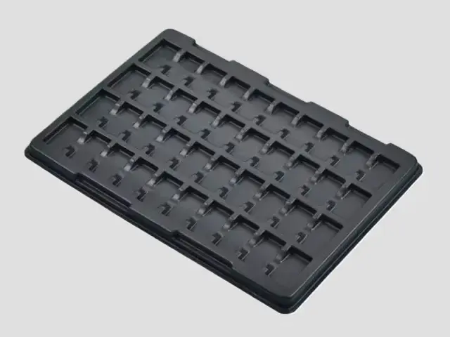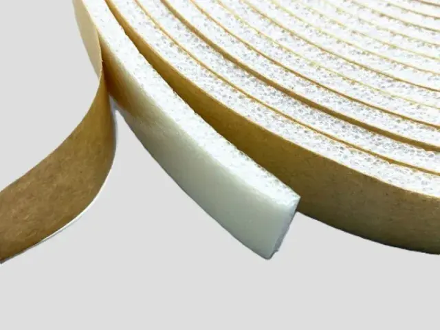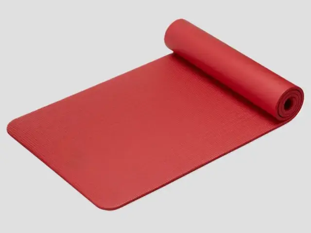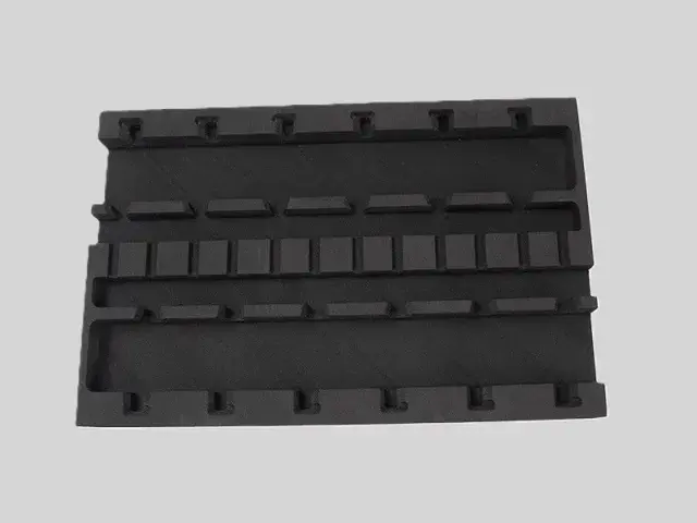

- Material: XPE foam, IXPE foam
- Expansion ratio: 25 times (40 kg/m³), 30 times (33 kg/m³)
- Thickness: surface layer 2–5 mm, bottom layer 20–40 mm (thickness can be customized)
- Colour: black + red, black + blue (colour can be customized)
- Flame retardant grade: UL94 HF-1
Customization
Made to order: density, thickness, colour and shape to your drawing. Die-cutting, CNC routing, lamination to film or fabric, slitting and adhesive coating all run in-house, so the part we quote is a finished part, not just a sheet. How a custom part is cut and routed explains what to send with the drawing.
Regular material: MOQ 1,000 m², lead time 15–20 days from order confirmation. Custom parts are quoted from the drawing. A4 samples are free, shipping included.
A toolbox is only organised if every tool has one place to go. Tool box foam inserts are cut to the outline of each item, so the layout holds itself together and a missing tool is obvious the moment the lid opens. Bofeng builds these inserts as a two-layer construction: a thin coloured surface layer over a thicker base, which gives the cut-outs a clean edge and the tools a firm seat.
Features
- Two-layer build – a thin coloured surface layer over a 20–40 mm base, so cut-outs read clearly and tools drop into place.
- Shaped tool cavities – die-cut to each tool outline, so nothing shifts when the box is carried, tipped or dropped.
- Impact absorption – the thicker base takes the shock of a knocked or dropped case before it reaches the tools.
- Wear and retained fit should be assessed against the actual tools and handling duty; no fixed service life is implied.
- Easy to clean – the smooth, non-absorbent surface wipes clean of oil and swarf.
- Colour coded – black with a red or blue surface layer as standard, so a gap in the layout stands out at a glance.
Applications
- Automotive workshops – sockets, spanners and diagnostic kit held in numbered positions.
- Machine shops – gauges and cutting tools protected so calibration survives transport.
- Electrical and plumbing service – hand tools and meters organised in portable cases.
- Field service and maintenance – cases where a missing tool has to be spotted immediately.
- Photography and instruments – cameras, lenses and precision equipment in fitted cases.
Specifications for tool box packaging foam
A tool box foam insert is a die-cut part, so the sheet has to hold a cavity, keep its thickness and cut cleanly.
| Foam | Expansion | Apparent density | Single-layer thickness | Why this grade |
|---|---|---|---|---|
| XPE | 10–20× | 50–100 kg/m³ | 3–15 mm (heat-bonded 15–200 mm) | Use this XPE range as a starting point for tool retention. Verify insertion force with the actual tool geometry, then inspect the pocket edges and retention after the expected removal and replacement cycles. |
| IXPE | 20–30× | 33.3–50 kg/m³ | 0.1–15 mm | Fine-cell sheet for the lid liner and for thin interleaving between parts, where a firmer sheet would not close. |
Base material specifications are on the XPE, IXPE and IXPP material pages; finished products are on the XPE foam and IXPE foam pages. Tell us the load, the space available and the service temperature and we will confirm the grade against your drawing.
Why Choose Bofeng Foam
- Two-layer construction: thin surface layer over a 20–40 mm base.
- Flame-retardant grade available – UL94 HF-1.
- Black + red or black + blue as standard, further combinations on request.
- Die-cut to your tool layout from a drawing or a photographed tray.
- Samples and specification sheets available before production.
Where die-cutting stops and CNC routing starts, and what makes a routed cavity expensive, is covered in our die-cutting and CNC routing guide.
Tool-Box Inserts: Dimension the Pocket Around How the Tool Is Removed
Separate Location From Transport Cushioning
A tool-control tray makes each item visible and locates it. That does not automatically make it a validated transit cushion for the heaviest tool. Provide the toolbox, tool set, storage orientation and expected handling so the support path can be reviewed. Long tools and heavy heads may need different pocket details.
Approve Clearance and Finger Access
Test the actual tool, not just its nominal drawing. Allow for finish, handle variation and any retained accessories. A pocket that looks precise can force users to lever a tool out against the foam edge. Place removal access where it supports the intended grip without cutting away an essential retaining web.
Identify the Layer Functions
A contrasting top layer can show missing tools, while the base supports the pocket. Specify each layer, the bond, pocket depth and any retained bottom. Do not assume colour contrast provides peel-out behaviour; a routed insert and a user-cut layered sheet are different products. Check pocket edges, chips and the support below the deepest cavity.
Keep a Tool-Set Revision
Retain the approved tools, box version, cavity drawing and first sample together. Review replacements that differ in size or mass. Wear, contamination and cleaner exposure should be assessed for the actual duty rather than translated into an arbitrary number of years. Agree the repeat-order reference and any transport test separately.
For sample identity, dimensions and the acceptance record, use the first-article review checklist with the application-specific checks above.
Making a tool insert usable at the workbench
Locate the tools in their working configuration
Supply an actual tool list and identify removable batteries, fitted sockets, extension bars and protective caps. A catalogue outline may describe a bare tool while the user intends to store it with an attachment fitted. Show the closed toolbox dimensions and any hinges, ribs or catches that reduce the usable volume. The insert drawing should distinguish the perimeter that fits the box from the cavities that locate the tools.
Mark where the tool can be supported and which parts should remain accessible. For example, the user may need to grasp a handle without touching a cutting edge or move a battery latch without removing the entire insert. Confirm the intended removal sequence on the first article. If a two layer layout is proposed, make sure the upper tray can be removed using its intended lifting points with the lower tools in place.
Agree what a missing tool should look like
Where the insert is intended to support visual inventory, review it with all tools present and with selected tools removed. Ask the buyer to define whether cavity outlines, labels or contrasting layers are part of the approved construction. A shadow board effect is a layout feature, not a guarantee that every missing item will be noticed. Keep small accessories in identified positions so the insert does not encourage loose items to collect in larger cavities.
Record the cleaning materials and workshop exposure expected by the tool owner for compatibility review. Do not assume that resistance to one fluid demonstrates resistance to every oil, cleaner or solvent. Assess the proposed construction and cleaning method using representative samples. The acceptance record should include fit, removal, layer attachment and the condition of the case closure, alongside any package transport checks the buyer requires.
Conclusion & Inquiry
A well-cut tray is what turns a box of tools into a controlled kit. Packaging foam covers the wider range of inserts and trays, and shadow foam applies the same idea as a wall or drawer board. Contact us with your tool list or a photograph of the tray and we will quote a cut layout.