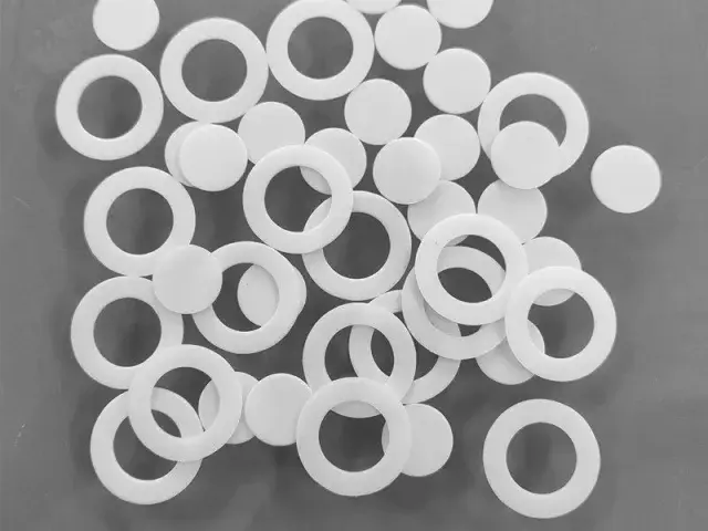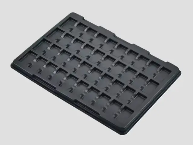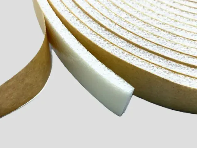

- Material: XPE foam, IXPE foam
- Expansion ratio: 25 times (40 kg/m³), 30 times (33 kg/m³)
- XPE single layers 3–15 mm; IXPE single layers 0.1–15 mm; thermally laminated multilayers 15–200 mm. Confirm the grade and construction against the drawing.
- Colour: black and gray (colour can be customized)
- Flame retardant grade: UL94 HF-1
Customization
Made to order: density, thickness, colour and shape to your drawing. Die-cutting, CNC routing, lamination to film or fabric, slitting and adhesive coating all run in-house, so the part we quote is a finished part, not just a sheet. How a custom part is cut and routed explains what to send with the drawing.
Regular material: MOQ 1,000 m², lead time 15–20 days from order confirmation. Custom parts are quoted from the drawing. A4 samples are free, shipping included.
Electronic products fail from the outside in. A screen cracks, a corner deforms, a port takes a knock — and the packaging is what decides whether any of that reaches the device. Bofeng die-cuts these inserts from XPE and IXPE foam, with cavities shaped to the exact outline of the product and its accessories, so the device is held on every face rather than resting on one.
Features
- Custom cavities – die-cut to the exact outline of the device and each of its accessories.
- Single or laminated build – XPE 3–15 mm or IXPE 0.1–15 mm as a single layer, or thermally laminated up to 200 mm where deeper cushioning is needed.
- Impact absorption – the closed-cell structure spreads shock away from screens, corners and ports.
- Low added weight – protects the product without adding meaningful shipping weight.
- Non-abrasive – a smooth surface; confirm contact compatibility with the actual housing or screen finish.
- Colour options – black and gray as standard, with other colours on request.
Applications
- Phones and tablets – edge and screen protection for retail and e-commerce packaging.
- Laptops – thicker pads set around the keyboard and behind the screen.
- Cameras and lenses – separate cavities for the body and each accessory.
- Games consoles and peripherals – fitted trays for consoles, controllers and headsets.
- Components and boards – tray layers that separate and cushion assemblies in transit.
Specifications for electronic product packaging foam
An electronic product foam insert is a die-cut part, so the sheet has to hold a cavity, keep its thickness and cut cleanly.
| Foam | Expansion | Apparent density | Single-layer thickness | Why this grade |
|---|---|---|---|---|
| XPE | 10–20× | 50–100 kg/m³ | 3–15 mm (heat-bonded 15–200 mm) | The standard insert grade, because the insert is a visible part of the pack, so surface finish and colour are part of the specification. The 50–100 kg/m³ band holds a die-cut cavity and should be evaluated in the actual pack for the required transit cycle. |
| IXPE | 20–30× | 33.3–50 kg/m³ | 0.1–15 mm | Fine-cell sheet for the lid liner and for thin interleaving between parts, where a firmer sheet would not close. |
Base material specifications are on the XPE, IXPE and IXPP material pages; finished products are on the XPE foam and IXPE foam pages. Tell us the load, the space available and the service temperature and we will confirm the grade against your drawing.
Why Choose Bofeng Foam
- Single layer XPE 3–15 mm or IXPE 0.1–15 mm, thermally laminated up to 200 mm where needed.
- Flame-retardant grade available – UL94 HF-1.
- Black and gray as standard, other colours on request.
- Die-cut to your device outline from a drawing or a physical sample.
- Samples and specification sheets available before production.
Surface resistance versus volume resistance, and which one a packaging specification is actually asking for, is set out in our conductive foam and ESD guide.
Approve the Pack-Out Before the Production Insert
Review the device, accessories and real box together. A cavity cut to a nominal outline cannot show whether a connector carries the load, a cable presses on the screen or the lid pushes the device into the base. Identify the surfaces allowed to support it and those that must remain clear.
Trace the Load Path
Mark product mass, fragile features, support points and centre of gravity where relevant. Restrain heavy accessories separately. Inspect finished surfaces after insertion and removal instead of assuming smooth foam cannot mark them. Determine whether the product is supported by foam, a retained bottom or the box floor.
Try packing and unpacking. Finger access reduces support at an edge, while a tight cavity can make an operator pull on a fragile part. A loose cavity permits movement. Review these trade-offs on a real sample before fixing the cutting tool.
Give the Test the Same Identity as the Sample
Record product version, accessories, container, grade, cavity construction, adhesive and packing sequence. Keep photographs of the open and closed pack and identify the tested specimen. Changing box, mass or pocket depth after validation can change the outcome even when the foam is unchanged.
Agree the distribution environment and protocol with the party responsible for shipment. Drop, vibration or other exposures need an agreed sequence and pass criteria for the actual product. Assess cosmetic and functional damage and internal movement against those criteria, not just whether the device switches on.
Density Does Not Provide a Cushion Curve
A cushion curve belongs to tested material at stated thickness, loading and drop conditions. It cannot be reconstructed from density, tensile strength or the name XPE. Another supplier's curve is not evidence for this insert. If curve data are required, identify the grade and conditions and arrange representative testing.
The insert design guide explains cut-through and retained-bottom geometry. Those are design inputs, not transport approvals. Do not reduce material solely because a first informal drop appears harmless.
Keep ESD and Mechanical Acceptance Separate
For sensitive contents, specify the electrical packaging requirement in addition to cushioning. Conductive or anti-static foam alone does not establish shielding or approval of the complete shipping pack. State the component-contact face and which packaging layer supplies each electrical function.
Send the drawing or sample, accessories, box dimensions, quantity, allowed contact surfaces, distribution conditions and acceptance method. We quote a construction and sample for evaluation, without inferring a guaranteed drop height or damage rate from the grade. Keep the approved pack-out and reference insert, and review changes before repeat orders.
Releasing an electronics insert with a defined packing configuration
Identify the equipment state during transport
Supply the actual equipment configuration that will be packed, including removable modules, fitted connectors and any shipping restraints. Mark sensitive surfaces and identify where the package designer permits the insert to support the product. A housing outline does not show a switch that must remain clear or a connector that should not be used as a locating feature. The cavity layout should reflect the shipped article rather than a simplified exterior model.
List accessories separately and give each item a designated location. If cables or power supplies share the case, include them in the first article. Check that the operator can remove the equipment using intended grip points without pulling on a connector or placing a loose accessory against a finished surface. These handling observations should be documented before the package is evaluated for distribution performance.
Keep cushioning and ESD evidence separate
Identify the role assigned to each packaging component by the product owner's ESD control plan. An insert may provide cushioning while another layer performs a specified protective function. Do not assume a resistance band proves shielding or that a fitted case is an approved ESD package. Match supporting documents to the actual material and construction, and keep the electrical protection assessment separate from mechanical fit.
Where the intended package is tested as an assembly, retain the complete configuration with the results. Include bags, separators, closures and the outer container rather than recording only the foam grade. A change to a protective bag or the placement of an electronic assembly may need review even when the insert remains unchanged. The product owner should determine the relevant reassessment and any limits on the approved arrangement.
Manage variants and returned packs
If a case is intended to carry several equipment variants, identify the combinations actually evaluated. Similar external dimensions do not establish that the permitted support surfaces and delicate projections are in the same locations. Use a packing schedule or layout reference so staff can recognise the correct configuration. For returnable packaging, define inspection and repacking instructions rather than assuming every returned insert remains equivalent to a new sample.
For production, retain the material description, cutting drawing, layer order and full package reference with the approved first article. If damage is reported, request the condition and arrangement of the complete package before it is altered. This supports a useful comparison with the evaluated configuration without turning a material data sheet into a damage free shipping guarantee.
Identify the approved packing sequence in the operator instructions.
Conclusion & Inquiry
Packaging foam covers the wider range of custom inserts and trays, and hardware packaging foam applies the same separation logic to metal parts. Contact us with your device dimensions and accessory list for a cut layout.