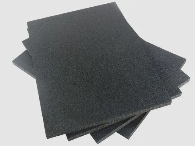

- Material: XPE foam (chemical cross-linked polyethylene)
- Expansion ratio: 3–40 times (26.8–300 kg/m³)
- Thickness: single-layer 3–15 mm; thermally laminated (multi-layer) 15–200 mm
- Width: 500–2000 mm (width can be customized)
- Colour: black, white, gray (colour can be customized)
- Cross-linking: chemical
- Conductive grade: permanent, 10³–10⁶ Ω. Anti-static grade: permanent, 10⁶–10⁹ Ω.
Customization
Made to order: density, thickness, colour and shape to your drawing. Die-cutting, CNC routing, lamination to film or fabric, slitting and adhesive coating all run in-house, so the part we quote is a finished part, not just a sheet. How a custom part is cut and routed explains what to send with the drawing.
Regular material: MOQ 1,000 m², lead time 15–20 days from order confirmation. Custom parts are quoted from the drawing. A4 samples are free, shipping included.
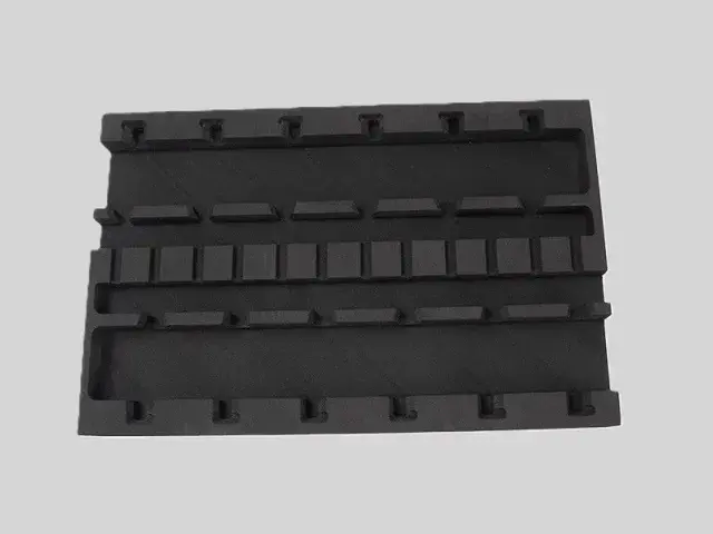
An anti-static blister tray is a thermoformed pocket tray – a sheet shaped into cavities that each hold one component. Where a foam tray is cut, a blister is formed, which makes it the cheaper option at volume and lets it be stacked and nested. Its purpose is the same: locate the part, cushion it, and keep charge off it.
Features
- Anti-static or conductive material: the sheet is produced so that charge built up on the tray drains rather than discharging into the component in the pocket.
- Locates each part: a formed pocket holds one component in a known position, which is what makes the tray usable for automated pick-and-place as well as for shipping.
- Stackable and nestable: trays are designed to stack loaded and nest empty, which cuts storage volume and freight cost.
- Light for its strength: lighter than a wooden or moulded alternative, so it is easier to handle and cheaper to move.
- Made to the component: pocket layout, depth and pitch are produced to the customer's drawing.
- Cost-effective at volume: the tooling is cheaper than injection moulding, so a blister is the economical choice for mid-volume programmes.
Applications
- Semiconductor and PCB component packaging
- Consumer electronics assembly and shipping
- Medical device component handling
- Automotive electronics and sensor packaging
- Logistics and warehousing of static-sensitive goods
- Laboratory sample and component storage
Specifications for anti-static blister tray
An ESD part is specified on two axes at once: the mechanical grade that holds the component, and the surface resistance that drains static.
| Foam | Expansion | Apparent density | Single-layer thickness | Why this grade |
|---|---|---|---|---|
| IXPE, conductive grade | 8–20× | 50–125 kg/m³ | 0.1–15 mm | A permanent conductive or anti-static grade, so the tray follows the component outline and has to stay conductive across the formed pockets. Surface resistance: conductive 10³–10⁶ Ω; dissipative 10⁶–10⁹ Ω. |
| XPE | 15–25× | 40–66.7 kg/m³ | 3–15 mm | The mechanical base layer, where the part also has to hold a shape or take a load rather than simply cushion. |
| IXPE | 8–20× | 50–125 kg/m³ | 0.1–15 mm | Thin, fine-cell IXPE sheet, and the plain base of the conductive grade above: the conductive grade is the same sheet with a conductive filler added, so the expansion range is the same. |
Base material specifications are on the XPE, IXPE and IXPP material pages; finished products are on the XPE foam and IXPE foam pages. Tell us the load, the space available and the service temperature and we will confirm the grade against your drawing.
Why Choose Bofeng Foam
We produce the tray material and the formed trays to the customer's pocket drawing, in anti-static and conductive grades, in the thickness the pocket depth requires. The resistivity bands and how to select between them are set out in the conductive foam and ESD guide, and the wider product family on the ESD foam hub. Where the part needs a foam cavity rather than a formed pocket, see conductive foam tray.
Foam Liners for Blister Trays: Confirm the Forming Process and the Contact Layer
Distinguish the Carrier From the Liner
A thermoformed rigid carrier and a cut foam liner are different components. State which part is being requested and the actual forming or converting route. A foam sheet capability must not be presented as evidence that any particular rigid tray or moulding process is supplied. Confirm the scope against the drawing.
Check Pockets and Extraction
Provide component geometry, pocket locations and the allowed contact surfaces. Review the complete carrier and liner so ribs, narrow bridges or a closing lid do not concentrate load. Evaluate insertion and extraction with the intended handling method, including any automated pick-up requirement.
Keep Electrical Evidence on the Real Surface
Specify resistance quantity, measurement conditions and the surface contacting the part. The carrier, foam and any film or adhesive may have different functions. Do not infer complete-package shielding from a conductive or anti-static liner reading.
Retain the Approved Combination
Keep carrier revision, foam, component set and test record together. Review changes to geometry or facing before repeat orders. Defined acceptance for fit, cut debris and electrical performance is more useful than treating tray colour or a material name as a certification.
For sample identity, dimensions and the acceptance record, use the first-article review checklist with the application-specific checks above.
Conclusion & Inquiry
Send the component drawing, the tray footprint and the annual volume, and we will confirm the material and pocket geometry. Contact us for samples or a quotation.