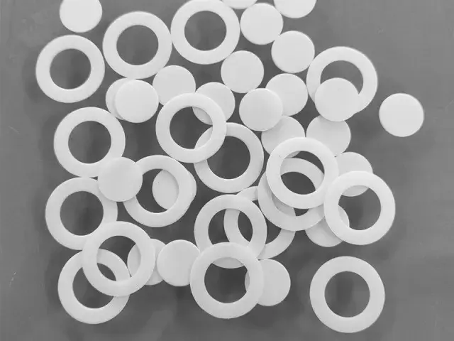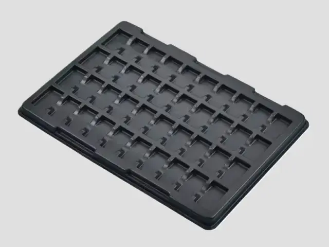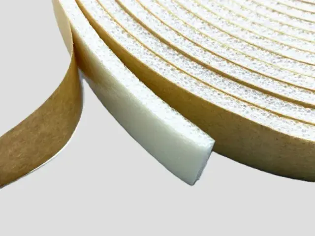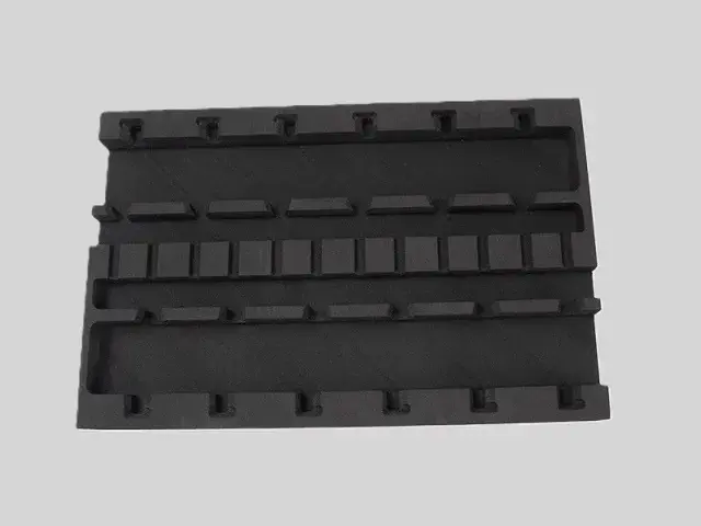
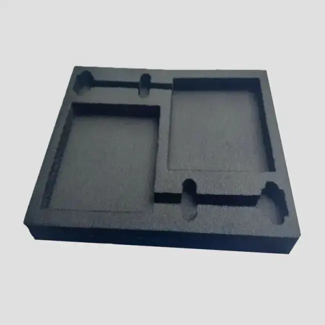
- Processing and moulding after foaming, using IXPE and related materials
- Conductive type resistance: 10³–10⁶ Ω; dissipative type resistance: 10⁶–10⁹ Ω
- Record the resistance test method, conditioning, contact face and applied contact; humidity and measurement conditions must be controlled.
- Service life is not declared; assess the loaded tray, handling and electrical requirements under agreed conditions.
- Designed and produced to the size provided by the customer
Customization
Made to order: density, thickness, colour and shape to your drawing. Die-cutting, CNC routing, lamination to film or fabric, slitting and adhesive coating all run in-house, so the part we quote is a finished part, not just a sheet. How a custom part is cut and routed explains what to send with the drawing.
Regular material: MOQ 1,000 m², lead time 15–20 days from order confirmation. Custom parts are quoted from the drawing. A4 samples are free, shipping included.
A conductive foam tray holds a static-sensitive part in a cavity cut to its shape, so the part is located, protected and electrically drained at the same time. Bofeng Foam produces the tray from conductive or dissipative foam, moulded after foaming and cut to the customer's cavity drawing.
Features
- Two resistivity grades: conductive at 10³ to 10⁶ Ω for a fast drain, and dissipative at 10⁶ to 10⁹ Ω where a slower, gentler discharge is wanted near sensitive devices.
- Stable value: the anti-static performance is a property of the material rather than a surface coating, so it is not affected by air, temperature or humidity and does not wear off in handling.
- Cushioning as well as conduction: the foam is soft enough to protect the part mechanically, so the tray replaces both the packaging and the shock protection.
- Cut to the part: cavities are produced to the customer's drawing so each component sits in its own location and cannot migrate in transit.
- Service life is not declared; assess the loaded tray, handling and electrical requirements under agreed conditions.
- Confirm an available recovery route for the complete tray in the destination market before making a recyclability claim.
Applications
- Semiconductor – ICs, chips and wafers in process and in transit
- Consumer electronics – boards and modules in assembly and shipping
- Medical device manufacturing – small, high-value components
- Aerospace and defence – components where a single discharge is unacceptable
- Automotive electronics and EV battery modules
Specifications for conductive foam tray
An ESD part is specified on two axes at once: the mechanical grade that holds the component, and the surface resistance that drains static.
| Foam | Expansion | Apparent density | Single-layer thickness | Why this grade |
|---|---|---|---|---|
| IXPE, conductive grade | 8–20× | 50–125 kg/m³ | 0.1–15 mm | A permanent conductive or anti-static grade, so the tray holds components in a fixed position and needs a conductive path across the whole tray. Surface resistance: conductive 10³–10⁶ Ω; dissipative 10⁶–10⁹ Ω. |
| XPE | 15–25× | 40–66.7 kg/m³ | 3–15 mm | The mechanical base layer, where the part also has to hold a shape or take a load rather than simply cushion. |
| IXPE | 8–20× | 50–125 kg/m³ | 0.1–15 mm | Thin, fine-cell IXPE sheet, and the plain base of the conductive grade above: the conductive grade is the same sheet with a conductive filler added, so the expansion range is the same. |
Base material specifications are on the XPE, IXPE and IXPP material pages; finished products are on the XPE foam and IXPE foam pages. Tell us the load, the space available and the service temperature and we will confirm the grade against your drawing.
Why Choose Bofeng Foam
We produce the trays to the customer's drawing, in conductive or dissipative grade, in conventional thicknesses of 3 mm, 4 mm and 5 mm, using IXPE and related materials. The resistivity bands and how to choose between them are set out in the conductive foam and ESD guide, and the wider range is on the ESD foam hub. Where the part travels loose rather than in a cavity, see anti-static crates.
Conductive Foam Trays: Keep Each Pocket and Electrical Contact Identifiable
Map the Components to Pockets
Provide component revisions, allowed contact surfaces, orientation and removal access. A tray with several cavities should locate each part without transferring load to a fragile lead, connector or finished face. Check the complete loaded tray and its container, not only an empty cut sample.
Agree the Conductive Requirement
Identify resistance quantity, method, conditioning and face, including any requirement for cut surfaces. A conductive foam description does not establish shielding or approval of the whole pack. Keep a facing or adhesive layer in the electrical review rather than testing only the bare core.
Inspect Cutting and Handling
Check pocket walls, debris, narrow webs and remaining base against agreed criteria. Use the real extraction motion so an operator is not forced to pull a fragile feature. Define how a damaged tray, changed fit or altered electrical reading will be handled. A laboratory material test does not establish a number of service years.
Confirm Repeat Supply and End of Life
Retain the material grade, cavity drawing, component set and approved sample. Changes to the contents or laminate require review. Reuse and local recyclability are separate questions: confirm a route for the complete tray with the relevant operator instead of promising universal recovery from the PE material name.
For sample identity, dimensions and the acceptance record, use the first-article review checklist with the application-specific checks above.
Conclusion & Inquiry
Send the component drawing and the sensitivity class, and we will confirm the grade, cavity layout and thickness. Contact us for samples or a quotation.