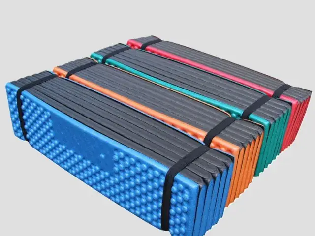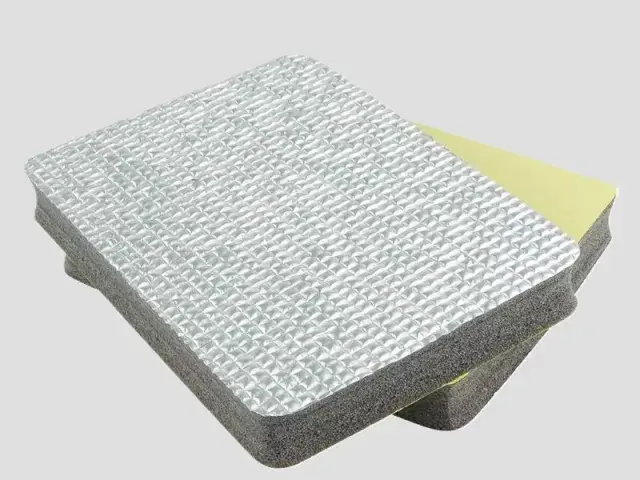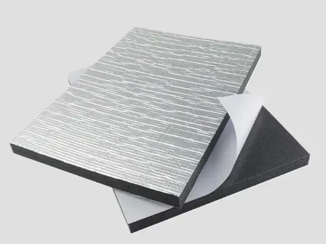

- Material: XPE, IXPE (polyethylene foam)
- Expansion ratio: 30 times (33 kg/m³)
- Width: 1 m, 1.2 m, 1.5 m (width can be customized)
- Thickness: 3 mm, 4 mm, 5 mm (thickness can be customized)
- Flame retardant grade: UL94 HF-1, GB8624-B1
Customization
Made to order: density, thickness, colour and shape to your drawing. Die-cutting, CNC routing, lamination to film or fabric, slitting and adhesive coating all run in-house, so the part we quote is a finished part, not just a sheet. How a custom part is cut and routed explains what to send with the drawing.
Regular material: MOQ 1,000 m², lead time 15–20 days from order confirmation. Custom parts are quoted from the drawing. A4 samples are free, shipping included.
A tee is where a pipe run branches, and it is the point where insulation most often fails. A rigid pre-formed sleeve cannot follow the geometry, so the junction is either left bare or wrapped badly, and the thermal bridge at the tee undoes the performance of the whole run. Tee pipe insulation foam is a thin, conformable XPE sheet made to close that gap.
Features
- Conforms to complex geometry: at 3 mm to 5 mm the sheet folds and laps around a branch take-off, following the saddle where three pipe surfaces meet.
- Closed-cell thermal performance: the high-density closed-cell structure blocks air movement through the insulation, which is what delivers the insulation value.
- Water-resistant surface: absorbs very little water, so the junction stays effective in damp plant rooms and buried or condensation-prone runs.
- Acoustic benefit: the foam also damps the flow noise and vibration that concentrates at a junction.
- Confirm temperature cycling and external exposure for the specified complete fitting construction; no generic UV or outdoor lifetime is declared.
- Flame retardant grades: UL94 HF-1 and GB8624-B1.
Applications
- Branch junctions on air-conditioning and chilled-water pipework
- Underfloor heating and hot and cold water distribution manifolds
- Chemical and pharmaceutical plant process piping
- Steam and chilled-water lines in industrial facilities
- Greenhouse and orchard irrigation headers
- Refrigerated transport and train carriage air-conditioning runs
Specifications for tee pipe insulation foam
A tee or a three-way joint is where a pipe wrap is hardest to fit, so the foam has to be soft enough to mould round the branch.
| Foam | Expansion | Apparent density | Single-layer thickness | Why this grade |
|---|---|---|---|---|
| XPE | 20–30× | 33.3–50 kg/m³ | 3–15 mm | Soft enough to wrap a branch without lifting at the crotch of the tee, while staying closed-cell against condensation. |
| IXPE | 25–35× | 28.6–40 kg/m³ | 0.1–15 mm | Finer cell and more conformable, for the tightest part of the joint. |
Base material specifications are on the XPE, IXPE and IXPP material pages; finished products are on the XPE foam and IXPE foam pages. Tell us the load, the space available and the service temperature and we will confirm the grade against your drawing.
Why Choose Bofeng Foam
We produce the foam at 30× foaming (33 kg/m³) in both XPE and IXPE, in 3 mm, 4 mm and 5 mm, in widths of 1 m, 1.2 m and 1.5 m, and to UL94 HF-1 and GB8624-B1. Supplying it in sheet rather than as a pre-formed fitting is deliberate: the installer cuts and laps the wrap to the junction in front of them, which gives a better seal than forcing a standard moulding onto a non-standard tee. Straight runs are covered with pipe insulation foam; the IXPE option is described on the IXPE foam page.
In-house conversion. The wrap is supplied in sheet so the installer can cut and lap at the tee. For repeat work we can slit it to the lap width, or die-cut a flat blank to your junction pattern, so the installer starts from a part that already follows the geometry. Regular sheet starts at 1,000 m²; cut-to-pattern parts are quoted from the joint drawing.
Which foam suits which line, and how thickness follows from the temperature difference, is covered in our pipe insulation guide.
Tee Fitting Insulation: Make the Branch Intersection a Defined Part
Measure All Three Legs
Provide main and branch dimensions, insulation space, neighbouring fittings and required installation access. A branch intersection concentrates seams where continuity can be difficult. Prepare a pattern or sample around the actual fitting rather than extending a straight-wrap dimension by assumption. Include the support and any removable component in the layout.
Choose the Assembly Route
State whether a cut pattern, joined pieces or another specified construction is required. Show which joints close first and how the remaining seams are reached. Trial fit without excessive tension or local crushing. A neat outer face does not prove continuity at the inner intersection; facing and adhesive need the same detailed review.
Review Thermal and Moisture Conditions
Give pipe temperature, ambient conditions and the project requirement. Water uptake, vapour migration and surface condensation are different issues. Check the branch crotch and the areas left for maintenance. A material value alone cannot establish the temperature of every surface on a completed fitting.
Keep a Fitting Reference
Approve the pattern, full build and seam arrangement with a representative sample or documented installation. Review changed branch sizes or nearby valves before repeat supply. No generic temperature-cycling life, UV result or condensation guarantee follows from a foam name. Keep material identification with the accepted fitting detail.
For sample identity, dimensions and the acceptance record, use the first-article review checklist with the application-specific checks above.
Detailing the insulation at a tee connection
Draw the branch and the neighbouring components
A tee piece should be specified from the actual junction rather than from the nominal size of a straight pipe. Supply the main run, branch, fitting and nearby clearances on a drawing or representative sample. Mark the direction of the branch and any adjacent valve, clamp or access point that affects assembly. The supplier needs to know whether the foam is supplied as separate cut pieces, a wrap or another confirmed construction. Do not assume a drawing of the pipe centreline describes the outside envelope of its fittings.
Identify the intended insulation on the adjoining straight runs. The tee component must be reviewed as an interface to those parts, including their jackets or closure layers where applicable. If the straight runs and junction are procured from different sources, assign responsibility for the connecting detail. A dimensional match at one location is not sufficient evidence that the complete junction can be closed and inspected after installation.
Make the assembly sequence explicit
Show which part is installed first and where the installer can reach the joining surfaces. If a piece must open around an existing line, include that condition in the brief instead of treating it as a new build installation. Confirm that the proposed splits, overlaps or closures can be completed without unplanned cutting on site. Where field trimming is allowed, the project owner should define its limits and the approval process for the resulting detail.
Trial the sequence with the actual junction or an agreed equivalent geometry. Observe the branch crotch, the transition onto each straight section and any area hidden after closure. Record visible gaps, crowding and local compression separately. The response to a poor fit should address the geometry and sequence, rather than relying on the installer to stretch or crush the foam until the outer surface appears smooth. Include the intended finishing materials in the trial.
Check continuity against the project design
Ask the system designer to review how the junction maintains the specified insulation and vapour control arrangement. The tee fitting introduces interfaces that are absent in an uninterrupted sleeve. A material conductivity value or water absorption limit cannot demonstrate the performance of a junction with an unapproved gap or closure. Condensation and thermal claims need the actual conditions and construction. Do not label an individual cut piece condensation proof without evidence for the installed system.
Where the project requires a fire or other classification, identify the document and the construction to which it applies. Do not transfer a rating from a straight material sample to an assembled tee automatically. Record any jacket, closure product or supporting component that is part of the evaluated detail. This keeps the purchasing specification aligned with the installation evidence instead of allowing a material family name to stand in for the whole system.
Retain a usable fitting schedule
Give each tee configuration an identifier linked to its main and branch dimensions, orientation and material choice. Photograph or retain the approved sample so the cutting layout can be reproduced. If a later junction has a different fitting body, access condition or adjoining insulation, review it as a changed configuration. For repeat orders, confirm the approved drawing revision and joining materials rather than ordering only a nominal pipe size and the word tee.
When several tee pieces look similar, provide an identification method that remains readable during installation. The main run and branch orientation should be clear from the component schedule and drawing. Confirm how the installer distinguishes configurations before the adjoining insulation is closed. This supports the approved assembly sequence and helps avoid an apparently minor exchange that changes the fit at the branch.
Conclusion & Inquiry
Send the pipe diameters at the junction and the line temperature, and we will confirm the sheet thickness. Contact us for samples or a quotation.