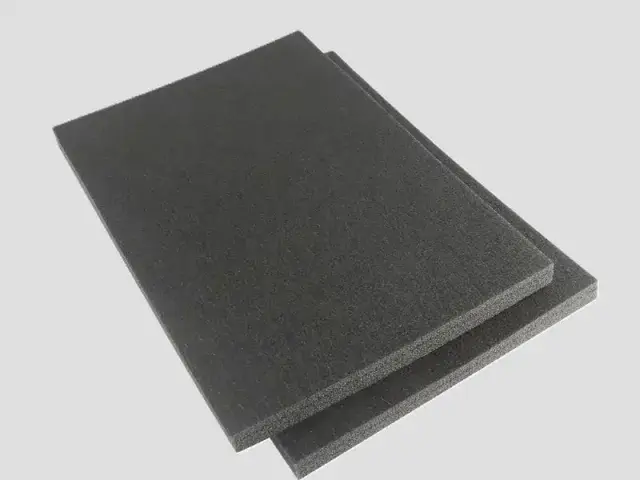
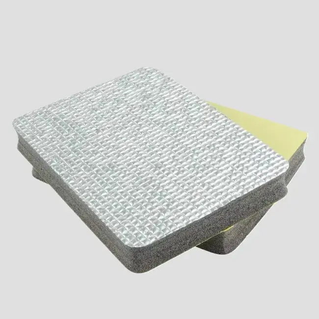
- Material: XPE, IXPE or IXPP foam, flame-retardant grades available
- Expansion ratio: XPE 3–40×, IXPE 3–40×, IXPP 5–25×
- Thickness: XPE single layer 3–15 mm, IXPE single layer 0.1–15 mm, IXPP single layer 1–6 mm
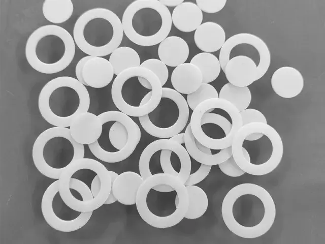
- Form: die-cut spacer, compression pad, end-plate pad, busbar insulator or slit strip
- Lamination: pressure-sensitive adhesive, PET film, flame-retardant film
- Flame-retardant grade: LOI 27, GB 8410 A0, UL94 V2 (grade-dependent)
Customization
Made to order: density, thickness, colour and shape to your drawing. Die-cutting, CNC routing, lamination to film or fabric, slitting and adhesive coating all run in-house, so the part we quote is a finished part, not just a sheet. How a custom part is cut and routed explains what to send with the drawing.
Regular material: MOQ 1,000 m², lead time 15–20 days from order confirmation. Custom parts are quoted from the drawing. A4 samples are free, shipping included.
A battery cell spacer is a mechanical part. It holds a gap between cells, takes up build tolerance, cushions swelling and vibration, and in some designs adds a dielectric layer between a cell can and a module structure. It is not a fire barrier, and it is not a thermal-runaway material. Those jobs belong to mica, aerogel, intumescent layers and the pack's thermal management system.
We supply XPE, IXPE and IXPP foam cut into spacers, compression pads, end-plate pads and busbar insulators, with or without adhesive or film. This page explains what the foam can do in a pack, what it cannot do, and what to measure before choosing a grade.
What the Spacer Has to Do
- Set the gap. Keep a defined distance between cells, or between a cell and a module wall.
- Take up tolerance. Compress slightly so the stack closes without over-stressing a cell.
- Cushion swelling and vibration. Absorb small movements over life and under road input.
- Insulate electrically. Add a dielectric layer where the design needs one, at the system voltage and pollution degree of the pack.
- Separate materials. Stop a cell can from rubbing against a module frame or another cell.
These requirements conflict. A thicker, softer pad takes up more tolerance but gives less gap control; a harder pad controls the gap but may not cushion. The design has to state which property is primary, and the pad has to be tested in the stack, not on its own.
Cell Formats and Spacer Shapes
| Cell format | Typical spacer | Main job | Watch |
|---|---|---|---|
| Prismatic | Flat pad between cells, end-plate pad | Gap control, tolerance, swelling | Compression force over the pad area; edge crush |
| Pouch | Thin spacer, frame or pad | Tolerance, cushioning, edge protection | Sharp cell edges; puncture risk |
| Cylindrical | Strip, holder insert or pad | Separation, vibration, gap filling | Point loading on the can; holder fit |
| Module end plate | Pad between the last cell and the plate | Tolerance and controlled preload | Force-deflection curve; compression set |
Material Choice
| Material | Single-layer thickness | Where it fits | Limit |
|---|---|---|---|
| XPE | 3–15 mm | General spacers, end-plate pads, module insulation | Rougher surface; check compression set at the design strain |
| IXPE | 0.1–15 mm | Thin spacers, tight gaps, smooth dielectric layers | Higher cost; thin sheets have less cushioning |
| IXPP | 1–6 mm | Higher-temperature zones, stiffer structural pads | Stiffer and less conformable; still not a fire barrier |
| Flame-retardant XPE / IXPE / IXPP | As base material | Parts that must meet a material flammability requirement | LOI 27 / UL94 V2 are material results, not a pack approval |
IXPE is often chosen for a thin dielectric spacer because it can be made down to 0.1 mm and has a smooth surface. XPE is the workhorse for thicker compression pads. IXPP is the option when the part sees more heat or needs to be stiffer — but a stiffer pad changes the force-deflection curve, so the stack design has to be rechecked.
Compression Pads: What to Measure
A compression pad is a spring. The properties that matter are the force-deflection curve at the design strain, the compression set after the expected time and temperature, and the relaxation over life. A data sheet that gives only density and tensile strength does not answer the question the pack engineer is asking.
Two practical rules. First, define the strain, not just the thickness: a 5 mm pad compressed by 1 mm is 20% strain, and the force at that strain is what the cell and the frame see. Second, test at the service temperature. A pad that holds force at 23 °C may relax much faster at 45 °C or above.
We can supply grade data and samples; the stack test is the customer's. Do not specify a pad from a single number on a data sheet.
Electrical Insulation
Polyethylene foam is a dielectric, and a PE spacer can provide a dielectric layer in a pack. But “dielectric” is not the same as “approved insulation”. The relevant questions are the system voltage, the pollution degree, the thickness after compression, the presence of moisture and contamination, and the creepage and clearance distances in the design.
If the spacer is part of the electrical insulation system, the pack designer has to verify it at the pack level, including the compressed thickness and the edges. We provide the material and the thickness; we do not certify an insulation system.
Thermal and Fire: What Foam Does Not Do
PE foam is a thermal insulator in the ordinary sense, but it is not a thermal-runaway barrier. It melts and burns at temperatures far below a cell thermal event. A pack that needs cell-to-cell thermal isolation uses mica, aerogel, ceramic or intumescent materials, and the choice is driven by a thermal-runaway test, not by a foam data sheet.
Our flame-retardant grades meet LOI 27, GB 8410 A0 and UL94 V2. Those results describe how the material behaves in a small-scale flame test. They do not mean the part survives a thermal runaway, contains a fire, or protects a cell. Do not use a flame-retardant foam as a substitute for a fire barrier.
Cutting, Lamination and Cleanliness
Battery parts are usually die-cut, and the cut quality matters more than it does in packaging. A ragged edge sheds particles, and a particle inside a module is a potential short-circuit path or a contamination defect. Use a sharp die, control the cut edge, and clean the parts before they enter the pack area.
Common laminations are pressure-sensitive adhesive, PET film and flame-retardant film. Adhesive adds a layer that must be compatible with the cell surface and must not creep at the service temperature. A film facing can improve cut-edge integrity and handling, but it also adds thickness tolerance. Tell us the assembly method and the cleanliness requirement before the die is made.
Specifications We Can Supply
| Property | XPE | IXPE | IXPP |
|---|---|---|---|
| Expansion ratio | 3–40× | 3–40× | 5–25× |
| Single-layer thickness | 3–15 mm | 0.1–15 mm | 1–6 mm |
| Thermally laminated multilayer | 15–200 mm | 15–200 mm | 6–100 mm |
| Apparent density | Grade-dependent, 26.8–300 kg/m³ | Grade-dependent; ask for the data sheet | |
| Water absorption | 0.2% or less to 0.4% or less, GB/T 1034 method 4 | Ask for the grade data | |
| Thermal conductivity | 0.040–0.095 W/(m·K), grade-dependent | Ask for the grade data | |
| Flame retardancy | LOI 27, GB 8410 A0, UL94 V2 (flame-retardant grades) | ||
| Lamination | Pressure-sensitive adhesive, PET film, flame-retardant film | ||
What We Do Not Claim
- No fire barrier. The foam does not contain a thermal runaway, stop fire propagation, or protect a cell. Use a material designed for that job.
- No battery-pack or OEM approval. We do not hold a pack-level qualification, a PPAP or an OEM material approval.
- No electrical insulation system approval. The material is a dielectric; the insulation system is the pack designer's to verify.
- No UN38.3 or transport approval. UN38.3 applies to the cell or battery, not to the foam; we do not provide a transport approval for a pack.
- No thermal-runaway test data. We do not publish cell-level thermal-runaway results for the foam.
Ordering, MOQ, Lead Time and Sample
- MOQ: 1,000 m² for standard roll or sheet. Die-cut spacers are quoted against the drawing and annual volume.
- Lead time: 15–20 days from order confirmation for standard material; a new die-cut part includes sample approval and tooling.
- Sample: an A4 piece is free; we pay the freight.
- What to send: the drawing, cell format, design strain and force target, service temperature, system voltage, flame requirement, cleanliness requirement and annual quantity.
FAQ
Can this foam be used as a fire barrier between cells?
No. PE foam is not a thermal-runaway barrier; it melts and burns below a cell thermal event. Packs that need cell-to-cell fire isolation use mica, aerogel, ceramic or intumescent materials. Flame-retardant foam is not a substitute.
Is the foam an approved electrical insulator?
It is a dielectric material, but we do not certify an insulation system. The pack designer has to verify the insulation at the system voltage, with the compressed thickness, edges, moisture and contamination in the real assembly.
What compression data can you provide?
We can provide grade data and samples. The force-deflection curve, compression set and relaxation at the design strain and service temperature should be measured on the actual stack; do not specify a pad from density alone.
Can you die-cut to a clean edge?
Yes, with the right die and process control. Tell us the cleanliness requirement for the pack area. A ragged edge sheds particles, and particles are a contamination and short-circuit risk.
Can you supply flame-retardant foam?
Yes. Flame-retardant grades meet LOI 27, GB 8410 A0 and UL94 V2 at material level. Those are not a pack-level fire or thermal-runaway approval.
Related Applications
EV battery foam · Automotive foam · Tape foam · Laminated foam · Cross-linked PE foam materials