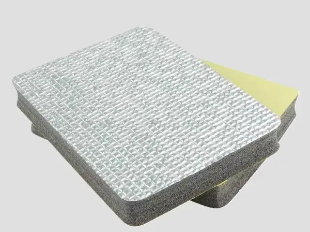

- Material: XPE foam + aluminum foil (aluminum film)
- Expansion ratio: 30 times (33 kg/m³)
- Width: 1 m, 1.2 m, 1.5 m (width can be customized)
- Thickness: single-layer 3–15 mm, thermally laminated (multi-layer) 15–200 mm
- Flame retardant grade: UL94 HF-1, GB8624-B1
Customization
Made to order: density, thickness, colour and shape to your drawing. Die-cutting, CNC routing, lamination to film or fabric, slitting and adhesive coating all run in-house, so the part we quote is a finished part, not just a sheet. How a custom part is cut and routed explains what to send with the drawing.
Regular material: MOQ 1,000 m², lead time 15–20 days from order confirmation. Custom parts are quoted from the drawing. A4 samples are free, shipping included.
Central air-conditioning duct insulation foam is a foil-faced XPE sheet wrapped around the outside of supply and return ducts. Its job is twofold: stop conditioned air losing its temperature on the way to the room, and keep the duct surface above the dew point so that condensation does not form and drip.
Features
- Low thermal conductivity: the closed-cell XPE core resists conductive heat gain, while the aluminium foil facing reflects radiant heat away from the duct surface. A reflective benefit depends on a suitable adjacent air space and surface condition; it is not implied by every foil-faced assembly.
- Condensation control: holding the duct surface above dew point is what prevents the sweating that stains ceiling tiles, corrodes ductwork and drips onto occupants below.
- Foil facing as a vapour barrier: a continuous aluminium facing can restrict vapour migration, but seams, edges, penetrations and the complete construction must be assessed.
- Light and conformable: unlike rigid board, the sheet bends around transitions, offsets and branch take-offs without special pre-formed fittings.
- Laminated thickness range: 3 mm to 15 mm as a single sheet, and 15 mm to 200 mm as a thermally laminated multi-layer build-up where a higher insulation value is required.
- Flame retardant grades: UL94 HF-1 and GB8624-B1.
Applications
- Commercial buildings – shopping malls, hotels and office towers
- Residential central air-conditioning systems
- Industrial workshops where temperature and humidity are controlled
- Hospitals, laboratories and schools
- Data centre and telecoms cooling distribution
Specifications for central air-conditioning duct insulation foam
Duct insulation works over a large surface, so thermal conductivity and water uptake drive the choice.
| Foam | Expansion | Apparent density | Single-layer thickness | Why this grade |
|---|---|---|---|---|
| XPE | 8–15× | 66.7–125 kg/m³ | 3–15 mm (heat-bonded 15–200 mm) | At 8×, 10× and 15×, conductivity limits are 0.084, 0.073 and 0.065 W/(m·K), respectively (GB/T 10297). Water absorption limits are 0.2%, 0.2% and 0.3% (GB/T 1034 method 4). These material results do not guarantee condensation control. |
| IXPE | 15–25× | 40–66.7 kg/m³ | 0.1–15 mm | Used on duct bends and flexible sections where a rigid sheet will not follow the run. |
Base material specifications are on the XPE, IXPE and IXPP material pages; finished products are on the XPE foam and IXPE foam pages. Tell us the load, the space available and the service temperature and we will confirm the grade against your drawing.
Why Choose Bofeng Foam
We foam the XPE core and bond the aluminium foil facing in-house, so duct insulation is supplied at 30× foaming (33 kg/m³), in widths of 1 m, 1.2 m and 1.5 m, from 3 mm single sheet to 200 mm laminated board, and to UL94 HF-1 and GB8624-B1. Widths, thicknesses and facings are made to order. The same foil-faced construction is used for air conditioner panel foam, and the facing options are set out on the laminated foam page.
Where a foil facing helps and where it does not — the facing needs an air space — is covered in our aluminium foil insulation foam article.
Air Duct Insulation: External Wrap or Internal Liner?
An external thermal wrap and an internal acoustic liner occupy different positions and answer different questions. This page concerns foam outside the duct. Moving it into the air stream requires a separate assessment of fire, surface integrity, cleanliness and air-system requirements; matching thickness alone does not establish suitability.
Make a Joint Plan Before Cutting
Rectangular ducts have wide faces, corners, flanges, hangers and access doors. Plan how sheets meet, how the facing remains continuous and how penetrations and removable sections are treated. A covered face does not compensate for an exposed strip at a flange. Check corners on a representative section: bending can reduce installed thickness or lift the bond.
If a support compresses the insulation, include that location in the thermal assessment. Record the actual build and fixing arrangement rather than assuming it performs like an uncompressed flat sheet. Detail access sections so maintenance does not leave a permanent gap.
Record Conditions Behind a Condensation Complaint
Collect surrounding air temperature and humidity, duct operating temperature and surface observations at wet and dry locations. Note start-up, shutdown and ventilation changes. Condensation depends on surface temperature relative to local dew point. Low foam water absorption cannot prove the outer surface will remain dry.
A pattern helps locate the problem. Wetness at a flange, seam, hanger or access panel calls for inspection of local continuity. Widespread wetness calls for reviewing the design conditions and installed build. These observations support an investigation; the project designer must still confirm the calculation and required construction.
Separate Foil Continuity From Reflection
A continuous foil facing with properly detailed joints can restrict vapour migration. Seams, edges and punctures are part of that assessment. Radiant reflection is a different mechanism and depends on an appropriate adjacent air space and surface condition. Foil trapped between contacting layers does not automatically supply the same reflective benefit.
Water uptake, water-vapour transmission and surface condensation are three measurements. State each requirement separately; a result for one is not evidence for another. The laminate, joints and installation all matter alongside the foam grade.
Inspect Before Concealing the Duct
Check coverage, corner thickness, adhesion, facing continuity and penetrations while accessible. Photograph details and retain the grade, batch and full construction. Inspect under the agreed operating conditions and document corrective work before closing ceilings or enclosures.
Send the layout, surrounding temperature and humidity range, operating conditions, space, facing and fire requirement for selection. No fixed thickness here guarantees absence of condensation or a whole-duct thermal value. Round pipework has its own pipe insulation guide; facings and bonding are covered in laminated foam options.
Detailing a duct wrap beyond the uninterrupted flat surface
Identify the complete duct assembly
Provide the duct material, section geometry and the operating conditions defined by the HVAC designer. Show whether the proposed foam is an external wrap, an enclosure component or another confirmed part of the system. Include the facing and any specified air or vapour control layer. A material conductivity result cannot establish the performance of an unspecified duct assembly, and a foil surface alone does not define a reflective insulation system.
Mark joints, corners, flanges, supports and access panels on the installation detail. These interruptions affect how the layer is fitted and restored. Ask the installer to review the available space and the order in which the pieces are applied. A flat sheet sample may resolve cutting and facing appearance while leaving a flange closure or maintenance opening entirely unreviewed.
Plan continuity and access
Identify which joints are intended to be sealed and list the products specified for those interfaces. Provide representative facing and substrate samples where adhesion is relevant. Trial the installation on an agreed detail and inspect the condition before it becomes concealed. Record the actual overlap, attachment and closure arrangement rather than summarising it as foil faced foam installed to ductwork.
Where a section must be removed for access, define how it is reopened and restored. Keep the relevant drawing and closure materials available to maintenance staff. A restored section should be checked against the same design intent as the original installation. The ability to peel back a facing does not establish that it can be repeatedly resealed with an unchanged result.
Separate thermal, moisture and acoustic questions
The designer should define the conditions and criteria used to assess thermal and condensation performance. Foam water absorption is not a test of vapour continuity at an installed joint, and a thermal material value is not a prediction of the surface temperature in every building. Retain the complete assembly and conditions with any calculation or test evidence. If the route or operating conditions change, identify the affected details for review.
If the enquiry includes noise control, define the actual noise path and the proposed function of the layer. Closed cell foam used as insulation or at an interface should not be described as a measured duct sound absorber without relevant evidence. Keep acoustic results tied to the evaluated system rather than transferring them from another insulation material or an unrelated assembly. This prevents separate engineering questions from being answered by the same generic claim.
Keep the supply record aligned with installation
Approve the material grade, facing, converted dimensions and installation details together. Identify the relevant project revision on the schedule and retain an approved sample or representative detail. Changes to a facing, adhesive, attachment or layer position require review even if the foam core is unchanged. Reorders should reference that approved construction so procurement and installation remain connected to the system that the designer actually assessed.
Identify who accepts site changes to laps, joints and access details. Record the approved revision before the installation is concealed so later maintenance can restore the intended construction.
Conclusion & Inquiry
Send the duct dimensions, the supply-air temperature and the ambient humidity the run passes through, and we will confirm the thickness and build-up. See XPE foam for the base material data, or contact us for a quotation.