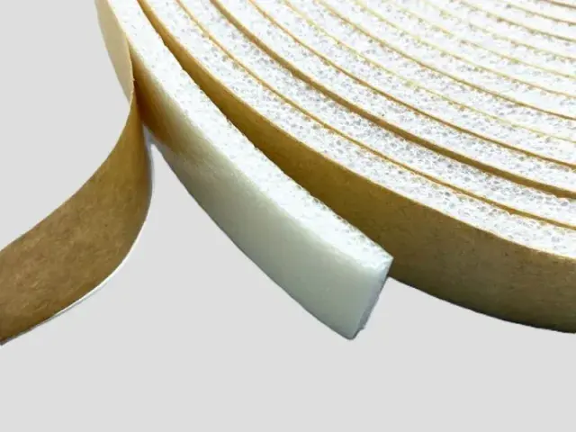

- Material: XPE foam + aluminum foil (aluminum film)
- Expansion ratio: 30 times (33 kg/m³)
- Width: 1 m, 1.2 m, 1.5 m (width can be customized)
- Thickness: single-layer 3–15 mm, thermally laminated (multi-layer) 15–200 mm
- Flame retardant grade: UL94 HF-1, GB8624-B1
Customization
Made to order: density, thickness, colour and shape to your drawing. Die-cutting, CNC routing, lamination to film or fabric, slitting and adhesive coating all run in-house, so the part we quote is a finished part, not just a sheet. How a custom part is cut and routed explains what to send with the drawing.
Regular material: MOQ 1,000 m², lead time 15–20 days from order confirmation. Custom parts are quoted from the drawing. A4 samples are free, shipping included.
Air conditioner panel foam is the sheet used inside an air-conditioning unit rather than around its pipework. It lines the inner face of the casing and the partition between the evaporator and the compressor compartment, where it does two jobs at once: it keeps the cold side cold and the hot side hot, and it absorbs the compressor and fan noise that would otherwise radiate straight off the cabinet panels.
Features
- Thermal separation: the closed-cell XPE core, backed with aluminium foil, reduces heat transfer through the casing, so the unit reaches temperature faster and cycles less.
- Noise absorption: the foam absorbs airborne noise inside the cabinet, cutting the radiated sound level compared with a bare metal panel.
- Light and easy to fit: the sheet weighs very little, cuts to the panel outline with a knife, and holds its shape when pressed into a shaped casing.
- Durable in service: resists aging, water and moisture, so performance holds up over the life of the appliance in a damp plant room or a humid climate.
- Laminated build-ups: 3 mm to 15 mm as a single sheet, or 15 mm to 200 mm thermally laminated where more insulation is needed.
- Flame retardant grades: UL94 HF-1 and GB8624-B1.
Applications
- Wall-mounted and floor-standing domestic air conditioners – casing liner and partition panels
- Commercial and central air-conditioning units
- Automotive HVAC units, where both noise and thermal control matter
- Refrigerators, freezers and other white goods
- Industrial cooling and process chiller cabinets
Specifications for air conditioner panel foam
Air conditioner panels are a sealing and insulating part as well as a structural one, and they sit in a condensing environment.
| Foam | Expansion | Apparent density | Single-layer thickness | Why this grade |
|---|---|---|---|---|
| XPE | 10–20× | 50–100 kg/m³ | 3–15 mm | For XPE 10x, 15x and 20x, compression-set limits are respectively 5%, 7% and 8% under GB/T 6669 at 23±2 °C for 22 h. Water-uptake limits are 0.2%, 0.3% and 0.3% under GB/T 1034 method 4; these do not establish unit condensation-cycle life. |
| IXPE | 20–30× | 33.3–50 kg/m³ | 0.1–15 mm | Smooth, thin sheet for a visible inner panel where the surface has to stay clean. |
Base material specifications are on the XPE, IXPE and IXPP material pages; finished products are on the XPE foam and IXPE foam pages. Tell us the load, the space available and the service temperature and we will confirm the grade against your drawing.
Why Choose Bofeng Foam
We supply panel foam at 30× foaming (33 kg/m³) with an aluminium foil facing applied in-house, in widths of 1 m, 1.2 m and 1.5 m, from 3 mm single sheet to 200 mm laminated board, and to UL94 HF-1 and GB8624-B1. Panels are cut to shape on request so they drop straight into the casing. The same foil-faced construction insulates the duct run – see duct insulation foam – and the base material is described on the XPE foam page.
Thermal conductivity by expansion ratio is set out in our XPE foam insulation guide.
Air-Conditioner Panel Parts: Control the Perimeter, Cut-Outs and Bond
Identify the Part Inside the Unit
A panel liner, perimeter seal and anti-rattle pad have different functions even if cut from similar sheet. Mark location, facing direction, mating surface and intended compression. Provide the drawing and material temperature rather than requesting an unspecified insulation thickness. Keep the role of the component separate from performance of the whole unit.
Check Functional Dimensions
Inspect holes, cut-outs, narrow webs and perimeter on a part made from the full laminate. Film and adhesive add thickness and can affect location. Agree critical dimensions and measurement conditions before tooling; a compressed calliper reading is not free thickness. Check that the complete part can be handled without tearing delicate features.
Trial Fixing and Service Access
State whether adhesive positions, retains or assists a mechanical fixing. Evaluate it on the real substrate and finish. Keep fasteners, drains, air passages and maintenance access unobstructed. A part that fits an open panel may move or become pinched when the unit closes, so inspect the actual assembly sequence.
Verify Unit-Specific Requirements
Condensation, noise, leakage and electrical functions require applicable assembly evidence. Absorption and conductivity do not establish unit energy or condensation results. Retain the approved drawing, grade, layer stack and acceptance record for repeat orders; review changes to the unit before assuming interchangeability.
For sample identity, dimensions and the acceptance record, use the first-article review checklist with the application-specific checks above.
Qualifying a panel pad in the air conditioner assembly
Identify the function of each foam location
An air conditioner panel can contain several foam pieces with different purposes. Mark whether each part is intended to seal an interface, separate contacting panels, fill a gap or provide another confirmed function. Show the mating surfaces and the closed assembly, including clips and fasteners. A single material description should not conceal the fact that one location is evaluated for fit while another is evaluated for a sealing or noise related requirement.
Provide the actual panel finish and identify any adhesive used to locate the foam. Include the process by which the foam is fitted before the panel is closed. If the component is applied to a plastic or coated surface, supply a representative production sample for adhesion review. A generic metal or plastic label does not describe every finish, cleaner or residue present on the production line.
Check the installed gap and closure
Record the intended gap and its variation as defined by the equipment designer. Review whether the pad contacts the correct surfaces when the panel is latched or screwed into place. Include the closing sequence because a panel can move relative to the pad during assembly. A hand squeezed sample does not establish the load applied by the actual fasteners or show whether the pad is displaced as the panel closes.
Look separately for poor contact, local overcompression and interference with adjacent components. If a sample does not fit, compare the drawing, supplied thickness and panel geometry before requesting a different foam grade. The material's compression data is relevant to selection but cannot establish the performance of an unspecified gap. The equipment owner should define the acceptable installed condition and inspection method.
Assess the claimed equipment result
If the purpose is noise control, the equipment owner needs a relevant assessment of the complete assembly. Closed cell foam at a panel interface should not be presented as a measured sound absorption treatment or a guaranteed reduction in equipment noise without supporting evidence. Record the actual pad locations and construction with any acoustic evaluation so the test does not become detached from the component that was fitted.
For sealing or insulation duties, identify the required test conditions and acceptance criteria separately. A water absorption limit does not prove airtightness of the installed panel, and a foam conductivity value does not establish the thermal performance of the whole enclosure. Where the design has fire or emissions requirements, request evidence for the selected grade and construction rather than using a broad claim about the foam family.
Retain the approved production arrangement
Include the converted dimensions, adhesive side, liner arrangement and orientation marks in the first article record. Trial removal of the liner and placement using the planned operator access or fixture. Confirm that the piece can be installed without unintended stretching or folding. Record any handling feature that forms part of the approved supply so it is not removed from a reorder as an apparently unimportant detail.
Keep the pad drawing, material grade, panel revision and assembly method together. Changes to the panel finish, fasteners, gap or adhesive require review even if the foam itself appears unchanged. When investigating a later issue, identify the location and actual failure mode before changing every pad in the equipment. This supports a targeted correction and avoids making unsupported promises about noise, condensation or product life.
Where several pads look alike, include an identification or placement reference in the assembly instructions. This helps operators reproduce the approved locations without assuming that every piece of the same colour has the same function.
Conclusion & Inquiry
Send the panel drawing, the unit's operating temperatures and the noise target, and we will confirm the thickness and facing. Contact us for samples or a quotation.