
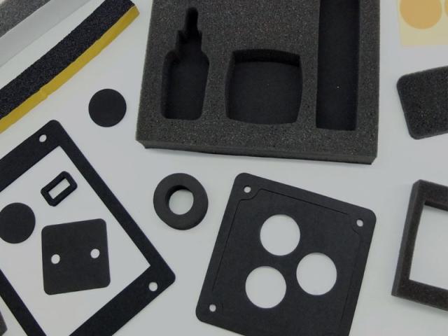
Matching an insert’s total thickness to the box’s internal height is not the end of the design. What decides whether the product survives a drop is something else: whether there is still foam under the product’s base.
Slot depth, bottom thickness and total thickness are three numbers, and any two of them fix the third. Most drawings give only the slot depth — and the same slot depth means a 10 mm bottom in a 50 mm insert and a cut-through in a 40 mm insert. One number, two constructions, two different load paths.
This page covers that one subject: how the layers are stacked, which layer the cut reaches, how much bottom to leave, and the part a specification sheet cannot answer. Which material and density to use is a separate question, covered in packaging foam and foam inserts.
Two numbers to decide, not one
Write the relationship out:
- Slot depth = product height − protrusion, where protrusion is how far you want the product to stand above the foam surface — for appearance, for grip, for fingers.
- Bottom thickness = total thickness − slot depth, the layer left between the product’s base and the underside of the insert.
- Bottom thickness of 0 is a cut-through.
With the total fixed at 50 mm, different product heights and protrusions land like this:
| Product height | Protrusion | Slot depth | Bottom thickness | Construction |
|---|---|---|---|---|
| 20 mm | 0 | 20 mm | 30 mm | Retained bottom |
| 30 mm | 0 | 30 mm | 20 mm | Retained bottom |
| 30 mm | 10 mm | 20 mm | 30 mm | Retained bottom, one third exposed |
| 40 mm | 0 | 40 mm | 10 mm | Retained bottom |
| 45 mm | 5 mm | 40 mm | 10 mm | Retained bottom |
| 50 mm | 0 | 50 mm | 0 | Cut-through |
| 60 mm | 10 mm | 50 mm | 0 | Cut-through, product stands 10 mm proud |
The most instructive pair is the 45 mm product with 5 mm protrusion and the 40 mm product with none: both give a 40 mm slot and a 10 mm bottom. If you want easier removal by exposing more of the product, the slot depth does not change and the bottom thickness does not change — only the product’s position within the slot does. Conversely, drop the total from 50 to 40 mm and the same 40 mm slot turns from “10 mm bottom” into a cut-through. Which is why a slot depth on its own is not enough: the total thickness has to be on the drawing too.
Cut-through: the product sits on the box floor
In a cut-through insert there is no foam between the product’s base and the bottom of the outer box. On a drop, the impact at the base is carried by the box and the product itself; the foam only works around the sides.
This is not a shortcut. There are three situations where it is correct:
- Shallow boxes. Where the box’s internal height is already less than the product height, retaining a bottom would press the product against the lid.
- Heavy parts. Where the base load is carried by structural parts, corner protectors or feet, and the foam’s job is lateral location.
- Products whose vulnerable face is not the base. Where the weak point is the front panel, the screen or a protruding part.
The cost is one sentence: the cushioning stroke at the base is zero. In all three cases something else in the structure has already supplied it.
Retained bottom: the product rides on foam
With a retained bottom there is a layer of foam between the product and the box floor, and on a drop that layer compresses first, stretching the impact over time.
There are two costs, both about thickness. The total must be greater than the product height, and the total is limited by the box’s internal height. So a retained bottom is not a free choice — it is squeezed out of the box:
Total = internal box height (or slightly less, if you want assembly clearance), and product height + bottom thickness + protrusion ≤ total. Those three numbers compete, and how much bottom you can have is settled by that budget.
The two constructions compared
| Cut-through | Retained bottom | |
|---|---|---|
| Support at the product base | Outer box (corrugated, wood or structure) | Foam |
| Cushioning stroke at the base | Zero | However far the bottom layer compresses |
| Demand on box internal height | Can approach the product height | Must exceed the product height |
| Slot depth | = product height | = product height − protrusion |
| Suited to | Shallow boxes, heavy parts, bases already carried by structure | Fragile parts, high-value parts, six-face cushioning |
| Main risk | Base impact passed straight to the product | If left too thin, bottoming out passes the impact just the same |
The last row is the point of the table. A retained bottom is not the same as cushioning. Leave 10 mm, and if the product bottoms out, the difference from a cut-through is a few milliseconds of delay.
How thick should the bottom be: three constraints
There is no general value. It is limited by three things at once:
- The single-layer ceiling. XPE 3–15 mm single layer, IXPE 0.1–15 mm, IXPP 1–6 mm. A bottom thicker than the ceiling cannot be one layer.
- The multi-layer ceiling. XPE and IXPE heat-laminate to 15–200 mm; IXPP to 6–100 mm. A 20 mm XPE bottom is at least two layers; a 20 mm IXPP bottom is at least four.
- The total-thickness budget. The bottom comes out of the box’s internal height, and every millimetre added to it is a millimetre off the protrusion or the product height.
As for how much compression counts as enough, this page gives no number, for the reasons in the section below. What can be said is the direction: the thinner the bottom, the less it can compress, and once it bottoms out the rest of the impact goes straight through. So the bottom should not be sized by the same number as the sides — the base usually wants to be thicker, because that is the face that usually hits the floor.
How a 50 mm insert is stacked
An insert of that thickness is not “a 50 mm board cut once”; it is several layers heat-bonded into one block. The number of layers follows from the single-layer ceiling:
| Material | Single layer | Minimum layers for 50 mm | One possible stack | Multi-layer ceiling |
|---|---|---|---|---|
| XPE | 3–15 mm | 4 | 15 + 15 + 15 + 5 mm | Heat-bonded 15–200 mm |
| IXPE | 0.1–15 mm | 4 | 15 + 15 + 15 + 5 mm | Heat-bonded 15–200 mm |
| IXPP | 1–6 mm | 9 | 6 × 8 + 2 mm | Heat-bonded 6–100 mm |
The layer counts differ so widely because the single-layer ceilings differ: XPE and IXPE reach 15 mm in one sheet, IXPP only 6 mm. So the same 50 mm insert has more than twice as many layer seams in IXPP. A seam is not necessarily a defect, but it is a feature of a heat-bonded part, and both the drawing and the inspection should know it is there.
Once the layer count is fixed, cut-through versus retained bottom becomes a question of which layers are cut. Take the XPE 15+15+15+5 stack:
- Bottom 0 (cut-through): all four layers cut to the product outline.
- Bottom 5 mm: the top three layers cut through, the bottom 5 mm layer left intact.
- Bottom 20 mm: only the top two layers (15+5) cut, the lower two left intact.
The last one looks odd written that way; it is simply “slot depth 20 mm” translated into layer order.
Which layer the slot depth falls in
Put a 40 mm slot into the XPE 15+15+15+5 stack and something happens that the drawing has to state: 15 + 15 = 30, so the next 10 mm goes into the third layer, which is 15 mm thick.
In other words the floor of the slot lands in the middle of the third layer — 10 mm of it removed, 5 mm left — with the fourth layer (5 mm) untouched. That is neither a cut-through nor an uncut layer; it is a half cut.
This decides the process, because flatbed die-cutting punches through and cannot make a half cut. There are only three ways to get a slot floor that lands mid-layer:
- CNC routing. The cut follows a programmed depth, so it can stop anywhere.
- Change the layer thickness. Replace a 15 mm layer with 10 mm so the slot floor falls exactly on a layer boundary, then die-cut whole layers.
- Cut first, bond after. Die-cut each layer to its own outline, then heat-bond the block — the thickness within a layer still cannot vary, but the layers can differ completely.
The trade-off between those processing routes is covered in die-cutting and CNC routing. The design-side rule is one sentence: when you draw the part, check whether your slot floor lands mid-layer; if it does, assume CNC, or change the layer thickness so that it lands on a boundary.
Bond-then-cut or cut-then-bond
The previous point opens a more general question of order. The same insert can be built two ways, giving quite different layer structures:
- Bond then cut. Heat-bond the layers into a block, then die-cut or route the whole. The outer contour is clean and the layers stay aligned, but the slot depth is limited to workings on the block, and any variation in depth has to come from routing.
- Cut then bond. Cut each layer separately, then bond. Layers can each have a different shape — the only way to build a structure with a hollow middle layer capped above and below — at the cost of aligning each layer during bonding, which gets slower as layers multiply.
So the layer count is not only a thickness question; it is also an alignment question. A 50 mm IXPP insert means nine layers and nine alignments; XPE needs four. That difference shows up in the price.
What to put on the drawing
A drawing that can go straight into production carries at least six items beyond the outline. Leave any one out and it comes back as a question during sampling or production:
| Item | Why it is needed | What happens without it |
|---|---|---|
| Total thickness and layer stack | Decides the bottom thickness and whether die-cutting is possible | Made as one layer, or with a different stack — different price and different behaviour |
| Cut outline of each layer | Layers can differ | One outline given, so every layer is cut through |
| Slot depth and bottom thickness | The same slot depth means two constructions at different totals | A single number is read as a cut-through |
| Protrusion | Fixes the product’s height in the slot and how easy it is to remove | You find out at sampling that it cannot be lifted out |
| Machine and cross direction | The two directions have different property ceilings, and the cutting direction changes the part | Properties do not match when the material lot changes |
| Outer box internal dimensions | The insert’s plan size is derived from them | The insert will not fit, or rattles once it does |
On machine and cross direction we will only say this much, because it is already written up as a layout rule elsewhere: the machine direction has the higher ceiling, and die-cut parts need allowance along their length. See automotive sound deadening foam for the full treatment. What matters here is that it must appear on the drawing — otherwise the same drawing produces different parts from two different lots.
What we do not conclude
“Is 10 mm of bottom enough” cannot be answered from a specification sheet. The reasons are specific:
- Specification sheets contain no cushion curves. Apparent density, Shore hardness, compression set, compression strength and dimensional change are all static material values, not “how much acceleration the product sees in a drop from a given height”.
- A cushion curve is not a material constant. It moves with thickness, density, contact area and drop height; the same foam in a different structure gives a different result.
- We do not have your drop-test data. How fragile the product is, which part is most vulnerable, and what acceleration it tolerates are known only to you and your customer.
That is why we do not give a general figure like “so many millimetres per kilogram” — a number without its conditions stops being true on the next product. What we can do is establish the conditions: product weight and centre of gravity, the most fragile feature, drop height and attitude, the construction of the outer box, and whether you already have packaging in service for a similar product. Given those, we propose a structure and your drop test confirms it.
One more boundary: this page is about the insert, not the packaging system. Outer-box strength, corner protectors, partition boards, blister tray stiffness and how the product is located inside the box are all outside it.
Common questions
Must an insert always retain a bottom?
No. Where the box has the height and the product base already has a load-bearing structure, a cut-through is the right answer. What to avoid is a bottom that is there but too thin — if it bottoms out under load, it is barely different from a cut-through.
How thick should the bottom be?
There is no general value. Start from how much the box height can spare, check it against the single-layer and multi-layer ceilings, and confirm by drop test. The direction is clear: the base usually needs to be thicker than the sides, because that is the face that usually lands first.
Is a cut-through insert unsafe?
No. It only means there is no foam cushioning on the base side; where the base is not impact-sensitive, or the box carries the load structurally, that is a reasonable design. What matters is how the whole pack behaves in a drop, not which of the two insert styles was used.
Can die-cutting make a slot that does not go through?
Flatbed die-cutting punches through, so a single layer cannot be half cut. To land mid-layer, use CNC routing, or change the layer thickness so the slot floor falls on a boundary and then die-cut whole layers.
How many layers is a 50 mm insert?
At least four in XPE or IXPE (15 mm single-layer ceiling) and at least nine in IXPP (6 mm). The count is arithmetic, not a process preference.
How does total thickness relate to box height?
Take the box’s internal height, or slightly less, and require product height + bottom thickness + protrusion ≤ total. The three compete, and the bottom is what that budget can spare.
Can you work from a sample with no drawing?
Yes. We can trace a physical part 1:1, or you can send one and we will trace it — but the layer stack and bottom thickness must be confirmed at sampling, otherwise the outline will match and the interior will be guesswork.
What Bofeng Foam supplies
Bofeng Foam produces XPE (3–40×, apparent density 26.8–300 kg/m³, single layer 3–15 mm, heat-bonded multi-layer 15–200 mm, width 500–2000 mm), IXPE (single layer 0.1–15 mm, heat-bonded multi-layer 15–200 mm) and IXPP (5–25×, single layer 1–6 mm, multi-layer 6–100 mm, maximum service temperature 140 °C).
Conversion is done in-house: die-cutting, CNC routing, heat bonding, lamination (aluminium foil, non-woven, flannelette, leather, film), adhesive backing, embossing and printing. Standard colours are black, white and grey, with custom colour matching. The plant is 10,000 m² with five production lines and 5,000 tonnes of annual capacity.
Send a drawing or a sample and we will reply with the layer stack and bottom thickness
See also packaging foam and foam inserts, die-cutting versus CNC routing, gift box inserts, wine packaging inserts, automotive sound deadening foam, XPE foam, IXPE foam and all cross-linked polyethylene foam materials.