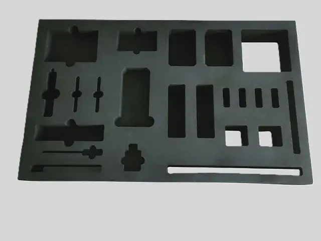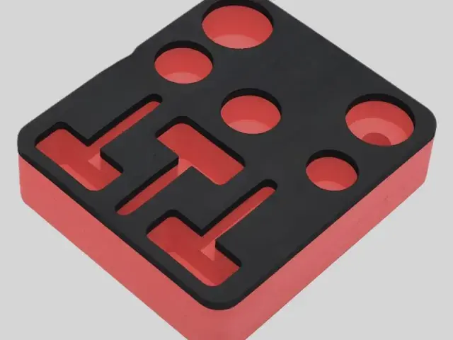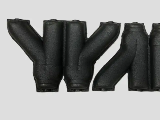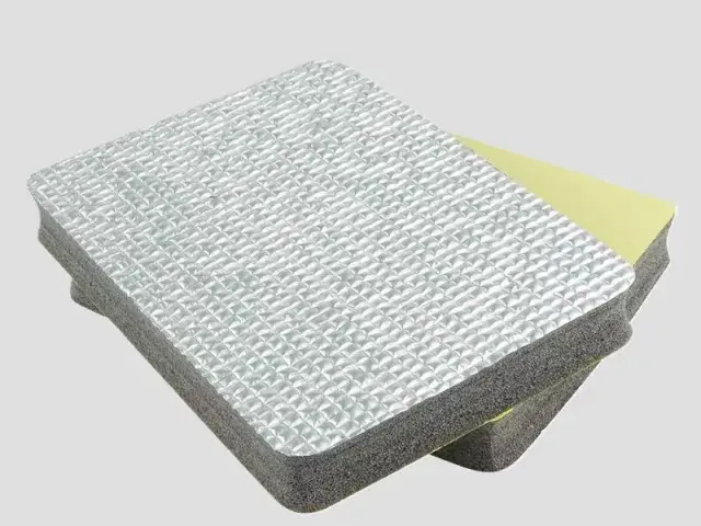

- Material: XPE foam (chemical cross-linked polyethylene)
- Expansion ratio: 3–40 times (26.8–300 kg/m³)
- Thickness: single-layer 3–15 mm; thermally laminated (multi-layer) 15–200 mm
- Width: 500–2000 mm (width can be customized)
- Colour: black, white, gray (colour can be customized)
- Cross-linking: chemical
Customization
Made to order: density, thickness, colour and shape to your drawing. Die-cutting, CNC routing, lamination to film or fabric, slitting and adhesive coating all run in-house, so the part we quote is a finished part, not just a sheet. How a custom part is cut and routed explains what to send with the drawing.
Regular material: MOQ 1,000 m², lead time 15–20 days from order confirmation. Custom parts are quoted from the drawing. A4 samples are free, shipping included.
Water gets into a tunnel at the joints. Segmental linings, construction joints and movement joints are all places where the structure is not continuous, and each one is a path for groundwater unless something compressible fills it. Tunnel seam splicing foam is placed in the gap before the concrete is poured, compresses as the joint closes, and stays compressed to hold the seal.
Features
- Elastic recovery – springs back after compression, so the joint stays filled even as the structure moves.
- Compressible – takes up the tolerance in the joint rather than forcing the concrete apart.
- Confirm temperature, water and chemical exposure against the actual joint materials and project requirement; no unrestricted underground or outdoor resistance is declared.
- Water-resistant – closes the joint against water penetration.
- Vapour permeable – lets water vapour escape so that condensation does not build up behind the seal.
- No special tooling – installed by hand, which matters on a tunnel programme where access is difficult.
Applications
- New tunnel construction – placed between formwork before the concrete pour, forming a continuous joint once the concrete has cured.
- Section joints – sealing between successive lining sections to keep the structure continuous.
- Tunnel rehabilitation – filling cracks and replacing failed sealants in ageing tunnels with leakage problems.
- Underground space – underground car parks and commercial concourses, not only road and rail tunnels.
Specifications for tunnel seam splicing foam
A tunnel or shaft joint strip has to follow an irregular seam, stay watertight and take movement between the segments.
| Foam | Expansion | Apparent density | Single-layer thickness | Why this grade |
|---|---|---|---|---|
| XPE | 10–20× | 50–100 kg/m³ | 3–15 mm | Water absorption no more than 0.2% with a tear strength of 2.5–6 kN/m, so the strip survives being pulled into a moving joint. |
| IXPE | 20–30× | 33.3–50 kg/m³ | 0.1–15 mm | More conformable sheet where the seam is uneven and the strip has to follow it closely. |
Base material specifications are on the XPE, IXPE and IXPP material pages; finished products are on the XPE foam and IXPE foam pages. Tell us the load, the space available and the service temperature and we will confirm the grade against your drawing.
Why Choose Bofeng Foam
- Closed-cell foam that compresses and recovers rather than taking a permanent set.
- Cut to the joint profile and width you specify.
- Water-resistant with vapour permeability, so the joint does not trap moisture.
- Supplied in the density and thickness matched to your joint movement.
- Samples and specification sheets available before production.
In-house conversion. The strip has to fit the joint, so we cut it to the profile and width you specify and can slit it from sheet to the exact lap width; where the seam is uneven, the more conformable IXPE follows it closely. Regular material starts at 1,000 m²; strip cut to the joint profile is quoted from the drawing.
What closed-cell foam actually absorbs, and why water-resistant is not waterproof, is measured in our water absorption guide.
Tunnel Joint Filler: Separate the Filler From the Waterstop and Seal
Identify Design Responsibility
Show filler, waterstop, sealant and supporting structure separately. This foam is a component, not a tunnel waterproofing design. The responsible engineer must define movement, exposure and acceptance for the joint. A closed-cell description does not establish watertightness of the assembly or suitability for every underground environment.
Review Placement Before Casting
If installed before concrete placement, specify location, restraint and protection during construction. Check formwork interfaces, ends and penetrations. A loose sample does not prove that the piece remains located during works or preserves the intended joint width. Inspect and record it before it becomes inaccessible.
Define Compression and Compatibility
Provide minimum and maximum joint conditions and the relevant temperature, water and chemical exposure. Agree tests on filler, sealant and adjacent materials where interfaces matter. Laboratory compression set does not establish movement-cycle life, hydrostatic sealing or compatibility with an unspecified tunnel chemical exposure.
Retain the Approved Detail
Keep joint section, dimensions, grade, fixing and construction sequence with approval. Record deviations during placement. A thicker piece or changed grade needs design review rather than an assumption of equivalence. Send the engineering requirement and drawing so the component supply can be confirmed to a defined scope.
For sample identity, dimensions and the acceptance record, use the first-article review checklist with the application-specific checks above.
Defining the foam component in a tunnel joint detail
Identify the joint and the responsible designer
A tunnel seam splicing enquiry needs the project joint detail, not merely a requested strip size. Identify the adjoining structures, the stage of construction at which the foam is installed and the role assigned to it by the designer. State whether it is a temporary positioning component, a separator, a backing or another confirmed function. Do not describe a foam strip as a structural seal or waterproofing system simply because it is placed near a tunnel joint.
Provide the relevant section drawing and identify the components supplied by other parties. Include the adjoining membrane, seal, grout, adhesive or mechanical restraint where it forms part of the detail. The compatibility and installation review should cover those actual interfaces. A generic foam property table does not approve a tunnel assembly, and the converter should not be expected to reconstruct the engineering intent from a photograph of an installed strip.
Define the installed dimensions
Show the nominal gap and the variation that the project designer expects the foam component to accommodate. Distinguish supplied dimensions from installed dimensions and identify the direction of any compression. Where the detail turns a corner or meets another joint, include that geometry explicitly. A straight sample can establish cutting and handling features but cannot demonstrate the suitability of every intersection on the project.
Mark the locations at which the component must be continuous and those at which a termination is intended. If separate lengths are joined on site, supply the approved joining detail for review. State whether the foam is attached before another layer is installed and how it is held during that operation. This turns the enquiry into a reproducible construction detail instead of an order for material that installers must adapt without a defined limit.
Plan access and workmanship checks
Ask the installer to review the proposed sequence in the available working space. Identify which surfaces must be prepared, which faces are bonded and when the finished location becomes concealed. If a component cannot be inspected after the next operation, define what needs to be checked before concealment. The acceptance process belongs to the project quality plan and should be agreed before material is delivered, rather than invented after a disputed installation.
For a representative installation sample, record the strip position, fit, joints and the condition of neighbouring materials. Note any local distortion or damage introduced during handling. If the installation method requires excessive stretching, unplanned cuts or changes to adjacent layers, refer the detail back for review. A visually smooth result does not prove that the intended geometry and continuity have been maintained.
Separate material selection from joint performance
The foam material's compression behaviour can inform selection, but it is not a measured joint movement capacity. Water absorption is not a hydrostatic leakage test of an installed seam. A flame classification for a material is not a classification for the complete tunnel construction. Identify the project requirement and the appropriate evidence for each claim rather than allowing several different performance questions to be answered by the same data sheet.
If the component contacts a project chemical or membrane, provide its identity and the proposed conditions for compatibility review. Avoid generic assurances about resistance to all construction chemicals. Where the designer requires testing of an assembly, use the actual arrangement and retain the component identification in the report. An alternative foam grade, facing or adhesive should be treated as a proposed change whose effect must be reviewed by the responsible party.
Prepare a controlled supply schedule
Assign identifiers to the different strip or fabricated part configurations and link them to the approved joint drawings. State the required delivery form and identify any orientation marks or packaging needed for installation. Keep the project revision with each order so material for an earlier detail cannot silently be substituted into a later one. Where several sections share a nominal width, identify the feature that distinguishes them for the installer.
Retain the approved sample, material description and relevant supporting documents with the project record. Agree who may authorise a change to the cut size, adhesive, facing or installation sequence. During a site investigation, request the joint identification and construction record along with photographs of the affected location. This evidence supports a meaningful discussion of fit and workmanship without making an unsupported promise that an individual foam strip prevents every possible tunnel leak.
Distinguish a supply deviation from a revised design
If an installed strip does not match the approved detail, first compare its identification, supplied dimensions and placement with the project record. Establish whether the material was supplied incorrectly, altered during installation or fitted to a changed joint. These possibilities call for different corrections. A request to send a larger strip should not bypass the designer's review of the actual joint geometry. Keep the proposed correction and the authorising party identifiable in the record. Where the foam is concealed by later work, arrange the necessary inspection before proceeding. This gives the project a traceable basis for accepting the correction without turning a material replacement into an unsupported statement that the completed tunnel joint has been tested or approved for leakage. Link each site correction to its approved joint drawing.
Conclusion & Inquiry
Flooring foam covers the construction and insulation range, and building construction foam covers the wider sealing applications above ground. Contact us with your joint detail and movement allowance and we will quote a supply.