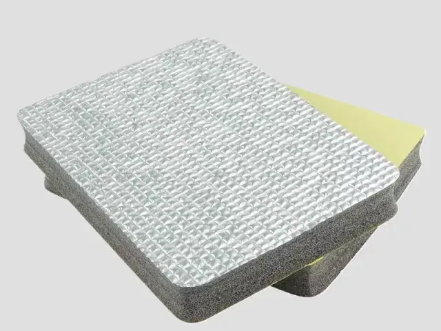

- Material: PU / PE foam core + conductive coating (carbon black / nickel / copper)
- Surface resistance: 10³–10⁶ Ω (customizable)
- Thickness: 1–20 mm
- Form: die-cut sheets, pads and gaskets
- Flame retardant: UL94 HF-1
- Colour: black
Customization
Made to order: density, thickness, colour and shape to your drawing. Die-cutting, CNC routing, lamination to film or fabric, slitting and adhesive coating all run in-house, so the part we quote is a finished part, not just a sheet. How a custom part is cut and routed explains what to send with the drawing.
Regular material: MOQ 1,000 m², lead time 15–20 days from order confirmation. Custom parts are quoted from the drawing. A4 samples are free, shipping included.
Static charge builds up wherever two materials separate: a tray lifted off a stack, a board slid out of a bag, a protective film peeled from a screen. On an unprotected component that charge finds the easiest path to ground, and the easiest path is often a signal line. A conductive foam divider gives the part a mechanical cradle and a controlled electrical path in the same piece — the foam holds the component where you place it, and the conductive grade drains charge away from it rather than through it.
This page is about the part you specify: dividers, separators, edge seals and gaskets cut from permanently conductive XPE and IXPE foam. It covers what the part has to do, how the resistance figure should be read before you compare suppliers, what a die-cut part will and will not hold, and where the material stops. The background on how surface and volume resistance are measured is in our conductive foam and ESD guide.
What the Divider Has to Do
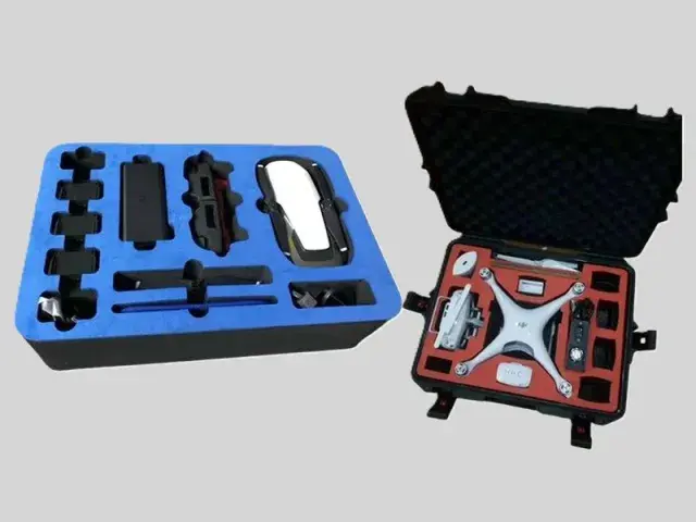
- Hold the component. The foam locates a board, a module or a connector block so it cannot move between the factory and the assembly line.
- Separate two surfaces. A divider stops a board from rubbing on a chassis, a shield can or another board, which is where most handling damage actually starts.
- Carry charge away. A conductive or static-dissipative grade gives accumulated charge a defined path to the enclosure instead of a path through a semiconductor.
- Keep its shape during assembly. The part has to survive being compressed, released and compressed again without taking a set that leaves the component loose.
- Touch the component without damaging it. A soft, closed-cell surface will not scratch a coated board, a display panel or a plated housing.
Most dividers carry two or three of these jobs at the same time, and the order matters. If the part exists to stop movement, specify the mechanical grade first and the resistance second. If it exists to drain charge from a moving sub-assembly, the electrical requirement drives the grade and the mechanical requirement only has to be met. A divider that was chosen on price alone usually fails on the property nobody wrote down.
Where It Sits in a Device
| Position | Job | Typical grade | Form |
|---|---|---|---|
| Display or screen edge | Seal the gap, cushion the panel, drain charge from the frame | Conductive IXPE, 8–20× | Die-cut gasket or strip |
| Chassis and enclosure seam | Fill the seam and give a ground path to the shell | Conductive IXPE | Die-cut strip |
| Between stacked boards | Hold board spacing and stop board-on-board contact | Static-dissipative IXPE | Die-cut frame or spacer |
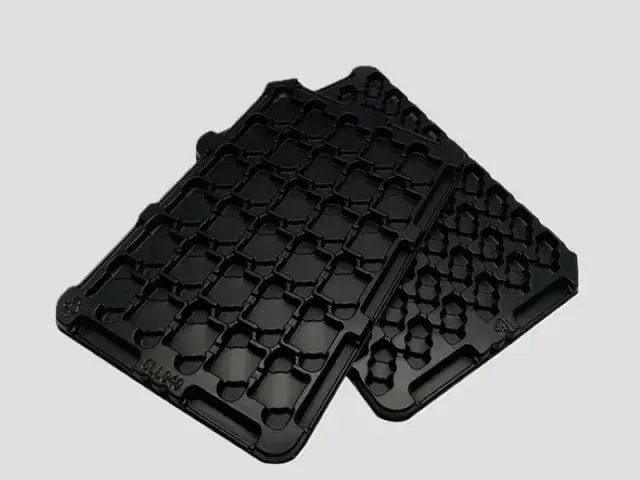
| Component tray or turnover box | Cradle parts through handling and transport | Conductive XPE, 15–25× | Die-cut or routed insert |
| Battery compartment | Hold the pack and isolate it from the shell | Static-dissipative IXPE | Die-cut pad |
| Cable and connector routing | Keep cables off a hot or moving part | Conductive IXPE | Die-cut strip |
Two positions on that list are often confused. A component tray insert is a handling part: it lives inside a tote and its job is to stop parts touching each other, so it is usually a firmer XPE grade cut from 10–20 mm sheet. A product divider is a part of the finished device: it stays in the assembly, so it has to meet the device's service temperature, its compression cycle and its thickness tolerance. The same foam family can serve both, but the acceptance criteria are not the same.
Conductive and Dissipative Are Two Different Specs
Conductive foam and anti-static foam are two grades of the same family, with two resistance bands. A conductive grade measures 10³–10⁶ Ω. A static-dissipative grade measures 10⁶–10⁹ Ω. Both are permanently conductive: the property belongs to the grade, so it does not depend on a treatment being renewed.
The difference decides which one you put next to a component. A conductive grade drains charge quickly and is used where a fast, low-resistance path to ground is wanted — trays, separators, ground paths in a chassis. A dissipative grade drains charge more slowly and is used where the part touches a powered assembly or a sensitive device directly, so that a discharge cannot arrive as a spike. Choosing the low band for a part that sits against a live board is a common mistake, and it is not corrected by making the foam softer.
Both bands are material ranges, not a per-part result. If your incoming inspection measures every lot, agree the test method and the sampling plan before tooling, because a range that is wider than your acceptance window will reject good material.
How the Resistance Figure Should Read
A resistance number without its measurement basis cannot be compared across suppliers. Three things decide whether two figures describe the same property: the quantity, the method and the conditions.
The quantity. Surface resistance is measured across the face of the foam; volume resistance is measured through its thickness. The two differ by orders of magnitude on the same sheet, so a quote that says only “10⁶ Ω” has not told you which one it means. For ESD parts we quote surface resistance. If the drawing or your inspection sheet specifies volume resistance, say so when you send it, and the grade will be confirmed against that method rather than against the default.
The method and the conditions. Contact area, electrode geometry, applied voltage and humidity all move the figure. Closed-cell PE foam also changes resistance under compression, so a reading taken on a loose sheet and a reading taken on an installed part are not interchangeable. State the standard and the conditions your quality team uses. If no standard is named, the two parties are measuring different things and the dispute only appears at the first rejected lot.
Compression, Contact and Set
A divider works because it is compressed. The foam has to push back with enough force to keep contact but not enough to distort the part, and it has to do that after hundreds of assembly cycles and a few years in service. That is a compression-set question, not a density question.
At 23 °C for 22 hours by GB/T 6669, the IXPE band used for ESD parts measures a compression set of 3% or less at 8×, 7% or less at 15× and 8% or less at 20×. A thinner, denser grade sets less but pushes harder; a lighter grade is gentler on the component and takes more set. Pick the pair your assembly can live with, and check the gap it has to fill rather than the thickness printed on the roll.
Heat changes the answer. A part that works at 23 °C but is fitted next to a power stage needs the grade checked at its service temperature, not at room temperature.
Die-Cutting and Assembly
Almost every divider is a die-cut part, and the cut is where a good material becomes a bad component if the tolerances are not agreed.
- Cutting. Rotary or flat-bed die-cutting for volume, CNC routing for prototypes and short runs. Both leave a clean edge on closed-cell foam.
- Tolerance. Give the fit dimension and the free dimension separately. A cavity cut to hold a board needs a clearance that the foam's own compressibility provides; a gasket that seals a seam needs an interference.
- Lamination. Pressure-sensitive adhesive backing, or a film or fabric facing, can be added where the part has to stay in place during assembly.
- Kitting. Parts can be supplied on a roll, in a sheet, or pre-separated in the order the line uses them, which removes a handling step at the customer end.
Send the drawing with the component dimensions, the gap the foam has to fill, the service temperature, the resistance band and the annual quantity. Cutting a trial part from the drawing costs far less than building a tool around the wrong interference.
Specifications We Can Supply
| Property | Conductive / dissipative IXPE | XPE |
|---|---|---|
| Expansion ratio | 8–20× | 15–25× |
| Apparent density | 50–125 kg/m³ | 40–66.7 kg/m³ |
| Single-layer thickness | 0.1–15 mm | 3–15 mm |
| Heat-bonded multilayer | 15–200 mm | 15–200 mm |
| Surface resistance | Conductive 10³–10⁶ Ω, dissipative 10⁶–10⁹ Ω | — |
| Compression set, 23 °C / 22 h | 3% or less to 8% or less, by expansion ratio (GB/T 6669) | 7% or less to 10% or less |
| Water absorption | 0.2% or less to 0.3% or less, GB/T 1034 method 4 | 0.3% or less to 0.4% or less |
| Thermal conductivity | 0.055–0.084 W/(m·K) | 0.055–0.065 W/(m·K) |
| Flame-retardant grades | LOI 27, GB 8410 A0, UL94 V2 (flame-retardant grades); UL94 HF-1 also available | |
| Processing | Die-cutting, CNC routing, lamination, pressure-sensitive adhesive backing | |
The material tables behind this summary are on the XPE, IXPE and IXPP pages, and the finished sheet ranges are on the XPE foam and IXPE foam product pages. If the drawing calls for a grade outside those ranges, tell us which property is driving it — usually one property can be met and the neighbouring one has to be traded.
What This Divider Does Not Do
- It is not an EMI shield. A conductive divider drains charge from a part; it has no attenuation figure in decibels, and it will not stop radiated emissions from leaving an enclosure. If the requirement is shielding, the enclosure needs a shielding design and the foam is at most a gasket in it.
- It does not replace a grounded workbench. A conductive tray or divider only works when it is connected to ground. An ESD part sitting on an insulated surface is an insulated part with a different colour.
- No per-part resistance guarantee. The figure we quote is the material's range. If your inspection measures every lot, the sampling and the method have to be agreed in writing, because we do not certify a reading taken by a method we have not seen.
- No aerospace, military or cleanroom qualification. Those applications appear in the market for ESD foam and the material is used there, but we do not hold aerospace approvals, military specifications or a cleanroom packaging certification, and we do not present any of them.
- It is not a structural part. A divider locates and cushions. It does not carry a load path, and it should not be the only thing holding a heavy assembly in position.
Put the same list in front of us and the answer is unchanged: we will tell you which of these the material can and cannot support, in writing, before a tool is cut.
Ordering, MOQ, Lead Time and Sample
- MOQ. 1,000 m² is the minimum for standard roll or sheet material. A die-cut part is priced from the drawing and the yearly quantity, because the die and the cut layout move the price harder than the foam does.
- Lead time. Allow 15–20 days after the order is confirmed for standard material; a first-off die-cut part additionally covers tooling and sample sign-off.
- Sample. The first step is a free sample: an A4 sheet of the chosen grade, sent with the freight paid, so you can measure the surface resistance with your own instrument before a die is cut. A cut sample of the actual profile is priced with the tooling.
- What to send. The drawing, the component dimensions, the gap to be filled, the resistance band, the service temperature, the flame requirement and the annual quantity.
FAQ
Can you supply a specific resistance value rather than a range?
We quote the band the grade is made in. Tightening a range below the material's own tolerance is a measurement agreement, not a material grade, so it has to be discussed together with the method your inspection uses.
Is conductive foam the same as anti-static foam?
No. A conductive grade is 10³–10⁶ Ω and a static-dissipative grade is 10⁶–10⁹ Ω. The dissipative grade is the safer choice where the part touches a live assembly, because it drains charge more slowly.
Will the foam keep its conductivity after die-cutting?
The conductivity belongs to the grade rather than to a surface treatment, so a cut part carries the same material through its thickness. The figure you measure on a cut edge still depends on your probe and on the contact pressure you apply, so a first-article check is worth doing.
Can the divider be supplied with adhesive backing?
Yes. Pressure-sensitive adhesive, film facings and fabric facings can all be added before die-cutting. Tell us which side is bonded and to what, because the adhesive choice depends on the housing material.
What is the thinnest divider you can cut?
From IXPE sheet the single-layer range starts at 0.1 mm and runs to 15 mm. Below roughly 0.5 mm the part becomes a film rather than a spacer, and the compression you can rely on drops sharply.
Related Applications
The same question — which grade, which band, which tolerance — appears across the ESD range. ESD foam covers the conductive and dissipative materials, conductive foam trays apply them to handling, and anti-static protection film covers the very thin end. On the material side, XPE foam and IXPE foam materials carry the property tables behind every number on this page, and the materials index shows where the three foam families sit against each other. If your requirement is a finished part rather than a sheet, send the drawing and the annual quantity and the cut layout will come back with the quote.